28
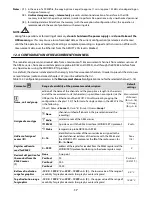
1. copy (if possible) the existing archive files to an external memory (a USB memory or the computer's disk)
2. format the internal memory
3. configure the recorder (manually, on-line, or off-line by restoring the configuration file copies if they have
been made by the user)
-
do not
establish communication with the device
simultaneously
from many applications of the same type
(ARSOFT-CFG/LOG)
- do not use sharp-edged objects to work with the touch screen
- avoid exposing the device to direct sunlight and other sources of intensive heat
- connection of the recorder to a USB port of a computer stops recording until the cable is disconnected and
blocks the performance of file operations available from the menu level and transmission of files with
measurement data via Ethernet from the ARSOFT-LOG level
17. RS485 COMMUNICATION INTERFACE (acc. to EIA RS-485)
The installation specification for the RS485 interface is the following:
- maximum cable length - 1 km (observe the installation guidelines, chapter 2, sub-items b, c, and d)
- maximum number of devices in a RS485 line - 30, in order to increase the number, use RS485/RS485 amplifiers
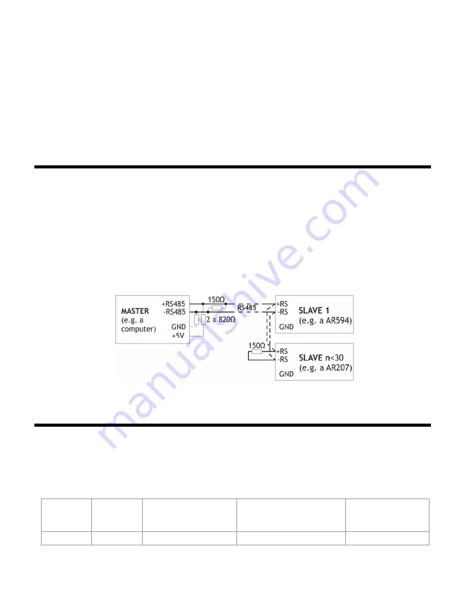
- termination and polarizing resistors when the MASTER is at the start of the line (Fig. 17):
- at the start of the line - 2 x 820 Ω to the ground and +5 V of the MASTER and 150 Ω between lines
- at the end of the line - 150 Ω between lines
- termination and polarizing resistors when the MASTER is in the center of the line:
- at the converter - 2 x 820 Ω, to the ground and +5 V of the converter
- at both ends of the line - 150 Ω each between lines
Equipment from different manufacturers that form the RS485 network (e.g. RS485 converters/USB) may have
integrated polarizing and terminating resistors; in such a case there is no need to use external elements.
Fig. 17. Pictorial diagram of the RS485 network
18. MODBUS–RTU SERIAL TRANSMISSION PROTOCOL
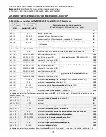
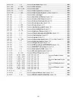
The MODBUS-RTU protocol is accessible to the RS485 interface and the USB. The parameters used by this service
are described in chapter 12.8. The MODBUS-RTU protocol in the Master mode (readout of data from Apar devices)
is available only for the RS485.
Character format : 8 bits, 1 stop bit, no parity bit
Available functions : READ - 3 or 4 for the Slave mode (4 for the Master mode) , WRITE – 6 (only in the Slave mode)
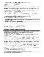
Table 18.1. Request frame format for the READ function
(frame length - 8 bytes):
address of
the device
function
4 or 3
address of the read
register from Table 20
(chapter 20)
number of read registers:
1
÷
32 (0x0020)
CRC check sum
1 byte
1 byte
2 bytes (HB-LB)
2 bytes (HB-LB)
2 bytes (LB-HB)
Example 18.1.
Reading of a register with address 0: 0x01 - 0x04 - 0x0000 - 0x0001 - 0x31CA
Содержание AR407
Страница 32: ...32 21 USER S NOTES...


