


2 - 14
Chapter 2 Operation
Feet
5
10
15
20
25
30
35
40
45
50
55
60
-5
-10
-15
-20
-25
-30
-35
-40
-45
-50
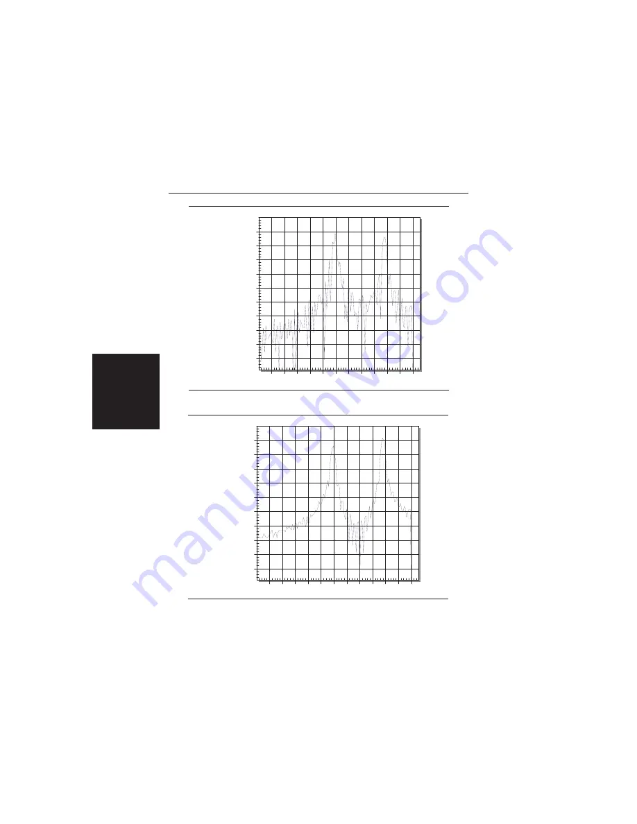
Return Loss (dB)
Distance To Fault
Figure 2-4.
Rectangular Windowing Example
Distance To Fault
5
10
15
20
25
30
Feet
35
40
45
50
55
60
-5
-10
-15
-20
-25
-30
-35
-40
-45
-50
Return Loss (dB)
Figure 2-5.
Nominal Side Lobe Windowing Example
Содержание Site Master S112
Страница 3: ......
Страница 15: ...This page is intentionally blank 1 7 Chapter 1 General Information...
Страница 52: ...2 36 Chapter 2 Operation Figure 2 10 Maximum Distance and Resolution vs Frequency Span...
Страница 81: ...3 14 Chapter 3 Screen Capture Program NOTES...
Страница 83: ......