74
www.analogway.com
USER MANUAL
USER MANUAL
USER MANUAL
USER MANUAL
USER MANUAL
USER MANUAL
USER MANUAL
USER MANUAL
Test image
Description
Line width
Adjust the line width in a test image using the slide bar.
Blue background
Show display areas that are not drawn in blue. Use when adjusting Keystone or
curved surface correction.
Canvas grid
Show white continuous grid across the composition. Also shows yellow X in the
middle of composition. Use for final adjustments.
Canvas lines
Show multicolored lines in selected angle. Use the checkboxes for defining the
line orientation. Use when adjusting display positions and bezel corrections.
Blend areas
Show display borders, edge blend area and edge blend center.
Use when adjusting edge blends.
Display borders
Show display borders with white lines. Use when adjusting keystone.
Display numbers
Show the display number of each display. Use to identify displays and make sure
they are properly connected.
(Selected) Display grid
Show grid and middle point of selected display. Use when adjusting angle and
curved surface corrections.
Control points
Show selected control points on the output. The selected control point turns
from green to red on the output. If selecting multiple points, only one point turns
red.
Layer borders /
Layer numbers
Show layer borders and/or numbers. Use to identify layers and help position
them in the show.
System info
Show server IP address, display number, output resolution and system runtime.
This test image is enabled on first boot, and after Media Server update.
Table 5 -
Test images
8.4
Positioning and Grouping Displays
1.
Select the display to control in the Display list.
2.
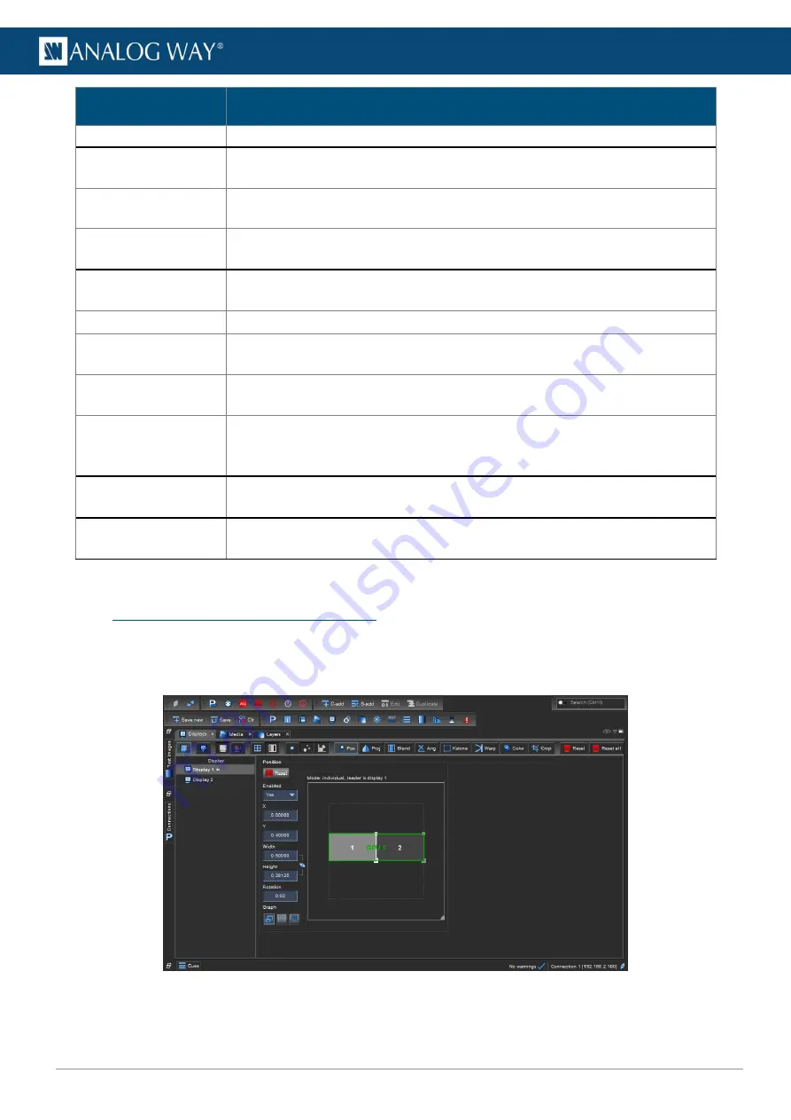
Open the
Positioning
panel and adjust the position, size, aspect ratio and rotation for the display.
Drag or scroll to adjust the values (hold
Shift
for precise adjustments).
Fig. 62 -
Positioning panel
3.
If needed, open the
Projection
panel to mirror and flip the image.


