UG-1055
EVAL-ADAU1777Z User Guide
Rev. 0 | Page 8 of 25
15054
-016
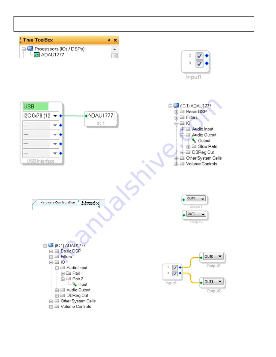
Figure 16. Adding an
To use the USB interface to communicate with the target
integrated circuit (IC), connect it by clicking and dragging a
wire between the blue pin of the USBi and the green pin of the
IC (see Figure 17). The corresponding drop-down box of the
USBi automatically fills with the default mode and channel for
that IC.
1505
4-
0
17
Figure 17. Connecting the USB Interface to an
CREATING A BASIC SIGNAL FLOW
To access the
Schematic
tab, where a signal processing flow
can be created, click the
Schematic
tab at the top of the screen
15054
-01
8
Figure 18.
Schematic
Tab
The left side of the schematic view includes the
Toolbox
, which
contains all of the algorithms that can run in the SigmaDSP.
From within the
IO > Audio Input > Pair 2
folder, select the
Input
cell (see Figure 19).
15
05
4-
0
19
Figure 19. Input Cell Selection
Click and drag the
Input
cell into the blank schematic space to
the right of the
Toolbox
15054-
020
Figure 20. Input Cell
Go to the
IO > Audio Output
folder and select the
Output
cell
1
505
4-
02
1
Figure 21. Output Cell Selection
Click and drag an output cell to the schematic. Repeat this step
to create two outputs (see Figure 22). Make sure that the output
cells are assigned to
OUT0
and
OUT1
, respectively.
15054-
022
Figure 22. Output Cells
Connect the cells together by clicking a blue output dot and
dragging to the green output dot of the next cell, connecting the
Input
2
to
OUT0
and Input
3
to
OUT1
15
0
5
4-
0
23
Figure 23. Connected Signal Flow
The basic signal flow is now complete with the stereo input/output.


