38
AM-TC10626LA
3
】
Mount tire
⚫
Lubricate tire bead, put the tire on the rim, leave mount/demount head to the edge of the rim,
depress the corresponding pedal to rotate turntable till tire mounted.
⚫
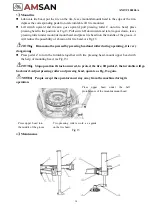
Lift switch upward and the arm goes upward, pull pressing roller C onto tire bead; place
pressing head to the position as Fig.13. Pull switch D downward and let arm goes down, leave
pressing roller under mount/demount head and press tire bead into the middle of the groove, it
will reduce the possibility of abrasion for tire bead. As Fig 13
NOTE
:
Rim cannot be pressed by pressing head and roller during operating, it is very
dangerous
;
⚫
Press pedal Z to turn the turntable together with tire pressing head, mount upper bead with
the help of mounting head. (as Fig.13)
NOTE
:
Stop operation if stuck occurred, to protect the tire, lift pedal Z, the turntable will go
backward. Adjust pressing roller and pressing head, operate as Fig.13 again.
NOTE
:
People except the operator must stay away from the machine during its
operation.
Press
upper
bead
under
the
ball
protuberance of the mount/demount head
Press upper bead into
the middle of the groove
4
】
Maintenance
Two pressing rollers work as a guide
on the tire bead.
Fig 13
Содержание AM-TC10626LA
Страница 1: ...PLEASE READ THE PRODUCT MANUAL ENTIRELY BEFORE INSTALLING OR OPERATING THE LIFT ...
Страница 22: ...Fig 34 21 AM TC10626LA 9 1 Column assembly 9 Exploded drawings ...
Страница 23: ...Fig 35 22 AM TC10626LA 9 2 Turntable assembly ...
Страница 24: ...Fig 36 22 AM TC10626LA 9 3 Gearbox motor assembly ...
Страница 25: ...24 AM TC10626LA 9 4 Body assembly Fig 37 ...
Страница 26: ...25 AM TC10626LA 9 5 Bead Breaker Cylinder Breaker Arm Assembly Fig 38 ...
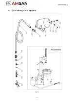
Страница 27: ...26 AM TC10626LA 9 6 Quick inflating system Optional Fig 39 ...
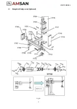
Страница 28: ...27 AM TC10626LA 9 7 Simple left help arm Optional Fig 40 INSTALL ...
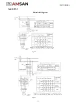
Страница 41: ...40 AM TC10626LA Appendix 1 Electrical Diagram Fig 40 Fig 41 ...
Страница 43: ...42 AM TC10626LA Appendix 4 MAINTENANCE LOG ...


