9
AM-TC10626LA
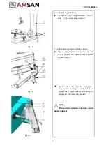
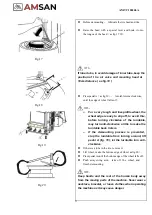
Fig.6-c
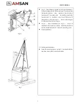
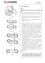
Fig.7
Step 3
,
Bead breaker cylinder location pin installation,
Pull out breaker arm M, till location pin V can be put into
the breaker arm hole
(
note
:
make sure the slot side of
location pin V is on outer side
)
Let arm M go back after
location pin V is installed
(
note
:
Insert Piston rod W
through hole of location pin V
),
Fasten connecting nut
X when arm M lay back. as fig.6-c.
Step 4
,
shovel installation, As fig.6- c
,
shovel Z
installation from inside to outside
,
install into the hole of
arm M, install flat washer Y, fasten X connecting screw.
Finish installation.
3.3.5 Lifting and installation
Take off screws by spanner
(
as Fig.7
)
Use hoist to lift the
machine, move pallet, locate the machine.
Содержание AM-TC10626LA
Страница 1: ...PLEASE READ THE PRODUCT MANUAL ENTIRELY BEFORE INSTALLING OR OPERATING THE LIFT ...
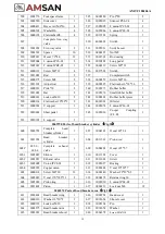
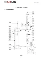
Страница 22: ...Fig 34 21 AM TC10626LA 9 1 Column assembly 9 Exploded drawings ...
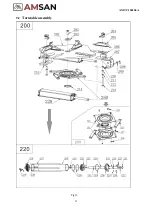
Страница 23: ...Fig 35 22 AM TC10626LA 9 2 Turntable assembly ...
Страница 24: ...Fig 36 22 AM TC10626LA 9 3 Gearbox motor assembly ...
Страница 25: ...24 AM TC10626LA 9 4 Body assembly Fig 37 ...
Страница 26: ...25 AM TC10626LA 9 5 Bead Breaker Cylinder Breaker Arm Assembly Fig 38 ...
Страница 27: ...26 AM TC10626LA 9 6 Quick inflating system Optional Fig 39 ...
Страница 28: ...27 AM TC10626LA 9 7 Simple left help arm Optional Fig 40 INSTALL ...
Страница 41: ...40 AM TC10626LA Appendix 1 Electrical Diagram Fig 40 Fig 41 ...
Страница 43: ...42 AM TC10626LA Appendix 4 MAINTENANCE LOG ...


