33
AM-TC10626LA
图
16
图
16
Fig
.14
Fig
.15
Fig
.16
⚫
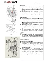
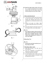
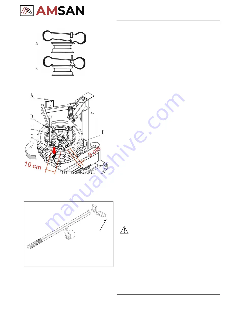
Adjust relative position between the tire bead and
mount/demount head, let the tire bead cross the
mount/demount head. At the end of the
mount/demount head, the tire bead should be
placed on the mount/demount head as fig. 14-A
;
At the beginning of the mount/demount head, the
tire bead should be placed under the ball
protuberance of the mount/demount head
(
as
fig.14-B
)
⚫
Press down the central part of the tire. Depress the
corresponding pedal to rotate the turntable
clockwise, making the lower tire bead fall into the
rim groove completely
3.2 Mounting upper bead
⚫
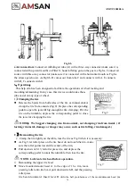
Adjust relative position between the tire bead and
mount/demount head (the same as a mounting
bottom bead)
⚫
An optional lever is recommended to mount
low-profile and run-flat wheels. As Fig.16 the arrow
sign show, these parts can be installed onto the
mount/demount
head.
(Washer
on
the
mount/demount head should be replaced when this
optional lever is used.)
⚫
Pull back the pressing roller D to the position as Fig
15, pull down switch A and let the pressing roller
press tire bead into the groove, the roller I (on the
optional lever) also help to press the tire bead
ahead of mount/demount head 3cm as Fig.15.
⚫
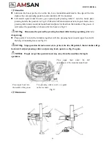
Depress motor pedal and turntable rotate clockwise
at one circle till tire upper bead meets the rim,
mounting finished.
NOTE
:
➢
It is extremely important, for the correct
functioning of the machine, that when
demounting or mounting a tire, the chuck
rotates
in
a
clockwise
direction;
anticlockwise is only for correcting the wrong
operation.
➢
People except the operator must stay
away from the machine during its
operation
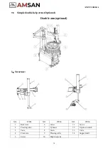
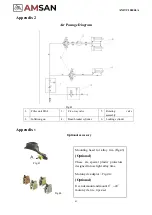
Optional lever with roller helps to press
(
Optional
)
Содержание AM-TC10626LA
Страница 1: ...PLEASE READ THE PRODUCT MANUAL ENTIRELY BEFORE INSTALLING OR OPERATING THE LIFT ...
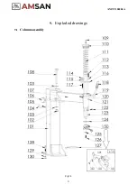
Страница 22: ...Fig 34 21 AM TC10626LA 9 1 Column assembly 9 Exploded drawings ...
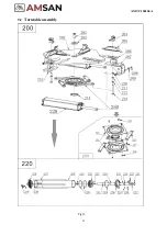
Страница 23: ...Fig 35 22 AM TC10626LA 9 2 Turntable assembly ...
Страница 24: ...Fig 36 22 AM TC10626LA 9 3 Gearbox motor assembly ...
Страница 25: ...24 AM TC10626LA 9 4 Body assembly Fig 37 ...
Страница 26: ...25 AM TC10626LA 9 5 Bead Breaker Cylinder Breaker Arm Assembly Fig 38 ...
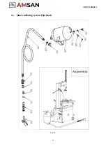
Страница 27: ...26 AM TC10626LA 9 6 Quick inflating system Optional Fig 39 ...
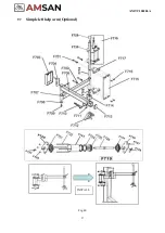
Страница 28: ...27 AM TC10626LA 9 7 Simple left help arm Optional Fig 40 INSTALL ...
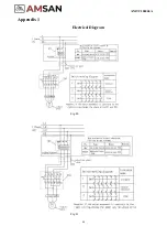
Страница 41: ...40 AM TC10626LA Appendix 1 Electrical Diagram Fig 40 Fig 41 ...
Страница 43: ...42 AM TC10626LA Appendix 4 MAINTENANCE LOG ...

