15
AM-TC10626LA
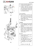
Fig.25
5.
Trouble Shooting
Malfunction
Cause
Solution
The chuck does not
rotate in any direction
1.
Power plug not inserted
2.
Incorrect connection in the plug
3.
Electrical supply not suitable
Check correct plugging and its
connection. (See cause 2 and 3)
Pressing
the
invertor
pedal down causes the
chuck t o t u r n i n an
anti-clockwise direction
Polarity inverted
Invert the connections in the power
plug
The chuck turns with
insufficient power
1.
Supply voltage wrong
2.
Driving belt loosen
1.
Check
the
correspondence
between the supply voltage and
that on the maker’s plate.
2.
Tighten the belt
The bead breaker does
not have sufficient power
to break the tire bead.
1.
The pneumatic
supply is not
connected to the machine.
2.
Insufficient
pressure
in
the
pneumatic system.
3.
The pressure reducer is closed or
badly
adjusted (for versions with this
device).
1.
Connect the pneumatic supply.
2.
Correct the supply pressure.
3.
Open or correctly adjust the
pressure reducer.
Other malfunctions should be checked and fixed by Professionally Qualified Personnel.
4.4.
Inflating Tire
Danger!
Inflating can be highly dangerous. Take precautions and pay
close attention to the procedures. Check if the compressed air is
well connected before inflating
!
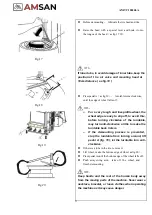
Inflating procedures are shown in Fig.25. The machine is
equipped with a gauge to read the pressure in the tire.
Connect the outlet of the gun to the air inflation valve.
Slowly press the switch on the inflating gun for several times
during inflation to make sure that the reading on pressure
gauge meets the manufacturer’s specifications. The pressure
should not exceed 3.5 bar.
If the pressure exceeds the limit, press the button on the gun
inflator so that the pressure goes down to what is required.
Содержание AM-TC10626LA
Страница 1: ...PLEASE READ THE PRODUCT MANUAL ENTIRELY BEFORE INSTALLING OR OPERATING THE LIFT ...
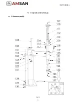
Страница 22: ...Fig 34 21 AM TC10626LA 9 1 Column assembly 9 Exploded drawings ...
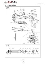
Страница 23: ...Fig 35 22 AM TC10626LA 9 2 Turntable assembly ...
Страница 24: ...Fig 36 22 AM TC10626LA 9 3 Gearbox motor assembly ...
Страница 25: ...24 AM TC10626LA 9 4 Body assembly Fig 37 ...
Страница 26: ...25 AM TC10626LA 9 5 Bead Breaker Cylinder Breaker Arm Assembly Fig 38 ...
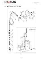
Страница 27: ...26 AM TC10626LA 9 6 Quick inflating system Optional Fig 39 ...
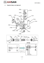
Страница 28: ...27 AM TC10626LA 9 7 Simple left help arm Optional Fig 40 INSTALL ...
Страница 41: ...40 AM TC10626LA Appendix 1 Electrical Diagram Fig 40 Fig 41 ...
Страница 43: ...42 AM TC10626LA Appendix 4 MAINTENANCE LOG ...


