background image

L0086, Rev. D 

AMS SENSIT II GLASS FRONT VRM VENDOR


5-2 

 
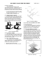
4.  Make sure the rail is level.   
5.  Align the round hole in the rail with the hole in the 

column and replace the screw. 

6.  Use these same steps for the other side. 
7.  Reinstall the tray, making sure the harness is routed 

over the top of the rail and all slack is draped to the 
outside of the rail. 


5.4 TRAY COLUMN POSITIONS 

Bottle tray column dividers are fastened in place and 

cannot be adjusted. The tray columns used for snacks and 
candy can be configured by the user from 5 to 10 columns 
wide.  Typically the vend columns are set to single (2.66”) 
or double (5.32”) width, to be used with the standard small 
or large helixes, respectively.  Single and double width 
columns can be configured in any arrangement on the tray 
by following the procedure below. 

Plan your tray arrangement before beginning to 

determine which extra parts may be required.  Contact your 
distributor to order the necessary parts. 


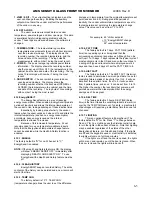
1.  Disconnect the harness and remove the tray.  Place the 

tray on a flat, stable work surface. 

2.  Reposition, remove, or add tray dividers in the desired 

locations.  To remove the divider, push rearward then 
lift.  Reverse the procedure to reinstall.   

3.  It may be necessary to remove a motor and helix in 

order to install some dividers.  Pull forward on the helix 
to remove it from the motor.  Press down and rearward 
on the top motor tab to remove the motor from the tray. 

4.  Reposition the motors to the center of each vend 

column, using the upper mounting position for the large 
helix and the lower position for the small helix.  It may be 
easiest to disconnect the motors from the harness first. 

5.  The harness has 10 sets of motor connections.  The first 

set of connections (at the end of the harness farthest 
away from the connector) is position 1, followed by 2, 3, 
and so on.  The last set (nearest to the wire connector) 
is position 0.  Facing the rear of the tray and starting at 
the right end, attach the harness connectors to the 
motors in order.  For double columns, use the even 
numbered connections and disregard the odd numbered 
connection.  (Example: If the first column on the left is 
double width, disregard position 1 and attach the 
connectors for position 2).  Each set of connectors has a 
wide and a narrow connector, corresponding to a wide 
and a narrow tab on the back of the motor. 

6.  Place the correct label in front of each column, 

according to the motor connections used. 

7.  Reconnect the harness, routing it over the rail and 

through the back of the column. 

8.  Reinstall the tray. 
9.  After changing the tray configuration, it will be necessary 

to reconfigure the motor matrix. Section 4.2.5 
Configuring Motors.  
 

5.5 CHANGING DIVIDERS 


1.  To remove, push rearward on the divider as far as it will 

go, then lift it up and out of the tray. 

2.  Reverse the removal procedure to reinstall. 


5.6 SNACK AND CANDY HELIX 

To remove, pull straight out on the helix to 

disengage the adapter from the motor. 
Reverse the removal procedure to reinstall. 
 

5.7 HELIX ADAPTER 


1.  To remove, twist the adapter to free the mounting leg 

from the locking tab. 

2.  Reverse the removal procedure to reinstall. 
 

5.8 HELIX EJECTOR 

The ejector’s function is to cause the product to fall 

sooner, and therefore stop the helix sooner. This will help 
retain the next product in the helix coil, especially if they 
are ‘difficult’ products 


1.  The helix ejector is pulled off and pressed on the spiral 

by hand. 

2.  The ejector is typically positioned half a coil or less 

from the end of the spiral.   

3.  The “fin” shaped portion is angled towards the front of 

the tray. 

4.  The best position and angle for the ejector is 

determined by test vending products. 


5.9 HELIX ALIGNMENT DEVICE 

The helix alignment device is installed against the 

left side of the large helixes to keep them centered in their 
columns.  


1.  To remove, grasp the front of the helix alignment 

device with pliers and pull or pry upward.  Take care 
not to lose the plastic mounting clips. 

2.  Reinstall by pressing the plastic mounting clips back 

into the mounting holes.  Note that the mounting 
flange goes toward the spiral. 


5.10 MOTOR POSITIONS 

Motor position can be changed sideways for 

different columns, and there are two mounting positions on 
the snack tray.  The lower and upper positions are used for 
the small and large spirals, respectively. 


1.  To remove, press down and rearward on the top 

mounting tab, then pull the lower mounting legs out of 
the mounting slots. 

2.  Reverse the removal procedure to reinstall. 
 

5.11 BOTTLE ALIGNMENT DEVICE 

The bottle alignment device will, in some cases, 

inhibit the rotation of bottles as they are vended.  It has 
two uneven-length legs.  It can be installed with either leg 
on top, depending on which works best. 


1.  To remove the bottle alignment device, remove the 

screws from the underside of the tray that hold it in 
place. 

2.  To reinstall, reverse the removal procedure. 

Содержание 39-VRM

Страница 1: ... AUTOMATED MERCHANDISING SYSTEMS 255 WEST BURR BLVD KEARNEYSVILLE WV 25430 304 725 6921 Fax 304 725 6983 INTERNATIONAL A M S S DE RL DE CV KM 9 CARR AL CASTILLO NO 8200 MPIO DE EL SALTO JAL MEXICO 45680 5233 36 88 07 17 Fax 5233 3 6 88 13 14 www amsvendors com e mail info amsvendors com ...

Страница 2: ......

Страница 3: ... 3 2 3 4 6 Keypad 3 2 3 4 7 Coin Return Button 3 2 3 5 REFRIGERATION CHILLER SYSTEM 3 2 3 5 1 Refrigeration Cycle Theory of Operation 3 2 3 5 2 Temperature Control 3 2 3 5 3 Refrigeration Controls 3 2 3 6 TRAY RAILS 3 2 3 7 TRAYS 3 2 3 7 1 Vend Motors 3 2 3 7 2 Helixes 3 2 3 7 3 Divider 3 3 3 7 4 Candy Pusher Bar 3 3 3 8 ELECTRICAL PANEL 3 3 3 8 1 Fuse Holder 3 3 3 8 2 Transformer 3 3 3 8 3 RF Fil...

Страница 4: ... 9 3 2 Secondary 6 4 6 9 3 3 Create Custom 6 4 6 9 4 Product Sensor 6 4 6 9 5 Speech 6 4 6 10 SALES BLOCKING 6 4 6 11 CLOCK SETTINGS 6 4 6 12 FREE VEND 6 4 6 13 AUXILIARY OUTPUT 6 4 6 14 DATA LOGS 6 4 6 15 ENERGYSENSIT 6 5 6 15 1 Enable 6 5 6 15 2 Clear History 6 5 6 15 3 Set Temp Chg 6 5 6 15 4 Set Patt Time 6 5 6 15 5 Set Hist Fact 6 5 6 15 6 Set Del 6 5 6 15 7 Lighting 6 5 7 TROUBLESHOOTING 7 1...

Страница 5: ... Pusher Bar Installation 5 3 Figure 5 4 1 5 Helix Tray 5 3 Figure 8 1 Replacing Control Chip 8 1 Figure 8 2 Refrigeration Unit Housing 8 1 Figure 8 3 Temperature Sensor 8 3 Figure 8 4 Harness Chip Programming 8 5 Figure 9 1 Typical Wiring Diagram Sheets 1 4 9 1 PUBLICATION NOTICE L0086D ECN 1564 08 18 2005 It is our intent to assist our customers with up to date documentation however this manual m...

Страница 6: ...L0086 Rev D AMS SENSIT II GLASS FRONT VRM VENDOR iv ...

Страница 7: ...very bin door will not affect the Sensit II system The sensors are located above the delivery bin and will not be blocked by the door Product that falls while the door is open will still pass through the beam 2 Shining a light at the detector will not allow vandals to receive free product Any tampering which changes the precise amount of light normally received will be treated as a successful vend...

Страница 8: ...ents United States Canada and Mexico 115 VAC 60 Hz International 230 VAC 50 60 Hz Basic Unit 3 amps 115 VAC 345 watts 1 6 amps 220 VAC 345 watts Refrigerated Snack 7 amps 115 VAC 805 watts 3 7 amps 220 VAC 805 watts Visi Combo 10 8 amps 115 VAC 1242 watts 5 6 amps 220 VAC 1242 watts 1 3 6 Refrigeration Specification HP R 134a 8 5 oz 24 kg 1 3 7 Coin Mechanisms and Bill Validators AMS vendors will ...

Страница 9: ...AMS SENSIT II GLASS FRONT VRM VENDOR L0086 Rev D 1 3 Figure 1 2 AMS 39 VRM Cabinet Dimensions Inches mm ...

Страница 10: ... 18 Pitch 1 25mm Opening 20120 24 24 Pitch 3 4 19mm Opening 3 Inch 76mm 21336 6 Pitch 3 1 2 88mm Opening Bottle Trays Only 4 Inch 102mm 21465 05 5 Pitch 3 1 4 82mm Opening 21465 07 7 Pitch 2 1 2 63mm Opening 21465 09 9 Pitch 2 50mm Opening 21465 10 10 Pitch 1 3 4 44mm Opening 21465 12 12 Pitch 1 1 2 38mm Opening 21165 15 15 Pitch 1 1 4 31mm Opening 1 5 Patent Disclosure This vendor and or certain ...

Страница 11: ...he vendor if service must be performed with the power on 3 Always keep electrical connections dry Do not place the vendor in or near standing water 4 Never use a worn or damaged power cord 2 2 2 Improper Grounding Some electrical components have a green or green yellow ground wire attached to a grounding point in the vendor If it becomes necessary to remove a ground wire during service note how th...

Страница 12: ... 6 Never attempt to lift or move the vendor by hand Always use equipment with the proper load rating Note that the Specification weight listed is empty weight 2 2 7 Other Improper Conditions Hazardous conditions can be created by improper use or service of the vendor WARNING Do not use electrical appliances inside the vendor unless recommended by AMS 1 Always reinstall any parts removed during ser...

Страница 13: ...on will have to be reprogrammed Refer to Section 8 1 for replacing the control chip 3 2 2 Mode Switch Pressing the mode switch refer to Figure 3 1 allows the user to get in to the computer s service mode to change settings access vend data and check error codes for troubleshooting Data is displayed on the front display panel and entered at the front selection panel Pressing the switch again or clo...

Страница 14: ... refrigerant is then sucked through an accumulator which traps any liquid refrigerant and allows it to evaporate before entering the compressor The refrigerant is then sucked into the compressor to be compressed completing the cycle 3 5 2 Temperature Control The evaporator fan runs continuously to circulate air within the cabinet A temperature sensor located near the evaporator measures the temper...

Страница 15: ...trol board when MDB devices are being connected or disconnected when the board is being serviced or before any wiring harness is connected or disconnected 3 8 2 Transformer The transformer reduces the input voltage to 24 volts AC for the control board 3 8 3 RF Filter The filter removes electrical noise from the power supplied to the 24VAC transformer to prevent interference with operation of the c...

Страница 16: ...L0086 Rev D AMS SENSIT II GLASS FRONT VRM VENDOR 3 4 ...

Страница 17: ...ny vendor using 120V service ELECTRICAL SERVICE REQUIREMENT FOR CE COMPLIANCE THIS EQUIPMENT IS INTENDED FOR USE ONLY IN PREMISES HAVING A SERVICE CURRENT CAPACITY OF AT LEAST 100A PER PHASE SUPPLIED FROM A DISTRIBUTION NETWORK HAVING A NOMINAL VOLTAGE OF 400 230V THE USER SHOULD DETERMINE IN CONSULTATION WITH THE SUPPLY AUTHORITY IF NECESSARY THAT THE SERVICE CURRENT CAPACITY AT THE INTERFACE POI...

Страница 18: ...ing holes over the threaded studs and reinstall the nuts Some devices may require spacers which are available from AMS Part Number 20258 5 Connect the wiring harness to the MDB harness from the control board If two devices are installed connect the second device to the validator 6 If a coin mechanism has been previously installed disconnect it from the control board MDB harness and connect it to t...

Страница 19: ...eet of the designated power outlet The power outlet should be accessible when the vendor is in position and the ventilation opening in the back of the vendor must be clear of obstructions 2 Allow at least 4 inches between the wall and the back of the vendor for air circulation 3 Make sure the vendor does not block walkways or exits 4 Do not place the vendor in a location where it can be struck by ...

Страница 20: ...ne on a new location it is important to allow the machine to cool to the operating temperature prior to loading products requiring refrigeration Depending upon the machine s initial temperature and ambient conditions it will take about 4 to 5 hours to accomplish this Normal practice is to place a machine on location and come back the next day to load it All products should be pre packaged 1 Plug i...

Страница 21: ...y 4 Be sure to push the extended slide rails back into the cabinet before closing the door Otherwise the slides may be damaged 5 2 2 Installation CAUTION An incorrectly installed tray can disengage from the rails and fall when extended It is recommended that installation be performed by at least two people 1 Fully extend the slide rails in the cabinet and hold in position 2 Move the ball carriers ...

Страница 22: ... 6 Place the correct label in front of each column according to the motor connections used 7 Reconnect the harness routing it over the rail and through the back of the column 8 Reinstall the tray 9 After changing the tray configuration it will be necessary to reconfigure the motor matrix Section 4 2 5 Configuring Motors 5 5 CHANGING DIVIDERS 1 To remove push rearward on the divider as far as it wi...

Страница 23: ... the product upright but not pinch or bind the product 5 15 CANDY PUSHER BAR INSTALLATION The candy pusher bar is an adjustable bar that mounts to any tray divider to keep tall candies from falling sideways refer to Figure 5 3 Four pusher bars are provided with the standard glass front vendor 1 Snap the pusher bar into the retainer 2 Rotate the pusher bar to accommodate the product Figure 5 3 Push...

Страница 24: ...L0086 Rev D AMS SENSIT II GLASS FRONT VRM VENDOR 5 4 ...

Страница 25: ...r used in place of the changer serial number in field CA101 6 3 FILL DISPENSE The FILL DISPENSE function allows the user to add coins to the changer or dispense coins from the changer 1 SELECT TUBE 1 5 To dispense coins press 1 through 5 for a 5 tube changer to dispense from tubes 1 5 Tubes are numbered starting with the lowest denomination The control will display the value of the coin being disp...

Страница 26: ...elections can be any combination of tray and column SAVE Press to save the new settings and return to the GROUP display EXIT Returns to the GROUP display without saving any changes 1 EDIT Press to move to the price setting display Enter a new discounted price for this group the group selections are kept intact SAVE Press to save the new price and return to the GROUP display EXIT Press to return to...

Страница 27: ... The factory default is Y for yes If set to Y the control will not allow a vend unless correct change can be returned to the customer If disabled the control will allow the customer to be short changed up to 1 00 6 8 3 Change Bill The factory default is N for no If set to Y the customer can insert a bill and receive a full refund in coins by pressing the coin return button Note that using CHANGE B...

Страница 28: ...n the control board other DEX functions cannot be used while the DoubleTalk LT is plugged in A dedicated cable could also be constructed 6 10 SALES BLOCKING The factory default is N for no The user can define up to four time periods each day during which specified selections will be blocked For each time period the user can select which days of the week blocking will be active All or any combinati...

Страница 29: ...isplaying HEALTH AND SAFETY ON To use EnergySensit the Health and Safety feature must be off 6 15 2 CLEAR HISTORY EnergySENSIT keeps a recorded history The entire contents of the history can be deleted and a new record will start at that time 6 15 3 TEMP CHG The factory default is 10 F TEMP CHG temperature change allows the user to set the difference increase in temperature from the original tempe...

Страница 30: ...L0086 Rev D AMS SENSIT II GLASS FRONT VRM VENDOR 6 6 ...

Страница 31: ...ill be displayed Refer to the next section for a description of error codes their causes and solutions 7 2 3 Error Code Causes and Solutions ERROR CODES CAUSES AND SOLUTIONS Top Level Error Code Sub Level Code Causes Solutions XX JAM ALL OK JAMMED XX OK Jammed product in helix broken jammed helix adapter helix caught on tray or divider frozen motor or broken gearbox Remove any jammed products and ...

Страница 32: ...any jammed products from the indicated vend columns To reset the error first enter service mode refer to Section 6 0 then select Tray Setup refer to Section 6 7 1 Press 1 then then 3 The control will attempt to run the jammed motors If the motor had been taken out of the motor matrix it will be re established in the matrix 7 4 WATER ACCUMULATION IN THE CABINET Water accumulating in the cabinet is ...

Страница 33: ...AC secondary side Insure primary side of transformer is receiving power If there is no 24 VAC on secondary side replace transformer Selection not configured in the motor matrix Reconfigure the motors Motor jammed Clear jammed motor and clear error code Vendor displays Please Make Another Selection Vend not sensed by sensor Clear fault in sensor boards or harness possible control board error Option...

Страница 34: ...style Gum and Mint trays Assy 20668 may be set to ON Set Home Switch to OFF Check for air leaks Close door tightly Moist outside air entering cabinet Check all gaskets for leaks Replace failed evaporator fan motor Check evaporator fan switch harness connection Evaporator frozen Check for evaporator fan motor not working Replace evaporator switch Adjust switch for positive contact with door Close d...

Страница 35: ...motors program the prices and re enter any other desired settings Refer to Section 6 0 Service Programming Figure 8 1 Replacing Program Chip 8 2 CLEANING THE REFRIGERATION UNIT AMS recommends cleaning the refrigeration unit at least twice a year under normal conditions more often in dusty environments CAUTION Always wear eye protection and gloves when cleaning vendor 1 Unplug the vendor 2 Remove t...

Страница 36: ... 3 Apply grease or similar lubricant to the door lock bolt threads and the door hinges as necessary 4 Wipe off excess grease No other lubrication is required 8 7 REPLACING FLOURESCENT BULBS 1 2 Unplug the vendor from the wall 3 Open the door 4 Turn bulb one quarter turn and at both ends at the same time slide out through the slots in bulb sockets 5 Remove one of the two black end caps from the cle...

Страница 37: ...does not start automatically choose START then RUN then type D setup exe where D is the name of your CD ROM drive 5 Follow the on screen instructions of the installation guide 6 After installation the AMS software may be left on the PC Store the CD as a backup 8 10 3 Startup After loading of software into the PC start up in the following order 1 Connect the cable connector to the PC serial port le...

Страница 38: ...election The lighting power saving feature is not affected USER MESSAGE may be up to 50 characters including lower case and additional punctuation marks not available through the keypad BLOCKING This screen displays four periods during the day when sales will be disabled Note that Sales Blocking and Delay Sales are used for different purposes For each period select the start time end time and day ...

Страница 39: ...ems BOOT LOAD 1 22 is displayed when the vendor is powered up while connected to the PC running this software Disconnect power to the vendor unplug the cable and restart the vendor UNEXPECTED APPLICATION RUNTIME ERROR DESCRIPTION PORT ALREADY OPEN occurs when this software is started while connected to the vendor the cable is connected to the wrong serial port or the PC is looking in the wrong pla...

Страница 40: ...L0086 Rev D AMS SENSIT II GLASS FRONT VRM VENDOR 8 6 ...

Страница 41: ...AMS SENSIT II GLASS FRONT VRM VENDOR L0086 Rev D 9 1 9 0 WIRING DIAGRAM Figure 9 1 Typical Wiring Diagram Sheet 1 of 4 ...

Страница 42: ...L0086 Rev D AMS SENSIT II GLASS FRONT VRM VENDOR 9 2 Figure 9 1 Typical Wiring Diagram Sheet 2 of 4 ...

Страница 43: ...AMS SENSIT II GLASS FRONT VRM VENDOR L0086 Rev D 9 3 Figure 9 1 Typical Wiring Diagram Sheet 3 of 4 ...

Страница 44: ...L0086 Rev D AMS SENSIT II GLASS FRONT VRM VENDOR 9 4 Figure 9 1 Typical Wiring Diagram Sheet 4 of 4 ...

Страница 45: ...since initialization CA404 Value of cash manually dispensed since initialization CA601 Number of DEX reads performed since initialization CA602 Number of door openings since initialization CA701 Value of cash discounts since last reset CA702 Value of cash discounts since init CA703 Number of cash discounts since last reset CA704 Number of cash discounts since init CA801 Value of cash overpay since...

Страница 46: ... since last reset PA205 Number of discounts since init PA206 Value of discounts since init PA207 Number of discounts since last reset PA208 Value of discounts since last reset PA401 Number of free vends since initialization TA201 Value of vend token sales since initialization TA202 Number of token vends since initialization TA203 Value of vend token sales since last reset TA204 Number of vend toke...

Страница 47: ...l Small Helix Part No 20536 Kit Cup Rail 4 Helix Part No 20723 Kit Cup Rail 3 Helix The cup rail is a flat plastic bar that can be placed inside the helix to provide a flat surface for rigid flat bottomed packages that otherwise do not stay upright when placed in a helix Examples would be drink boxes or bottles or individual serving cups of soup pudding etc Part No 20664 Kit Banking Spacer Part No...

Страница 48: ...L0086 Rev D AMS SENSIT II GLASS FRONT VRM VENDOR 11 2 ...

Страница 49: ...e returned properly packaged freight prepaid to AMS or to the authorized dealer or distributor from whom the equipment was purchased for verification of the defect Prior to returning any parts for replacement the customer is to contact the AMS Service Department at 304 725 6921 for return authorization AMS reserves the right to refuse any collect shipment This warranty applies only if the equipmen...

Страница 50: ...L0086 Rev D AMS SENSIT II GLASS FRONT VRM VENDOR 12 2 ...

Отзывы: