620LK Operation and Maintenance Manual – Rev. J – Updated January 2020
Page 17
13231 Rooster Springs Rd.
Austin, TX 78737
T:
(512) 858-4045
E:
amptec.com
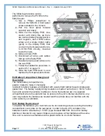
The following procedure can be
performed to remove the PCB from the
620LK meter:
1) Use a Philips screwdriver to
remove the 620LK’s 4 front panel
screws located in the corners.
2) Pull the front panel forward
carefully and slowly.
3) Slide out the display PCB. Use
caution with doing this, as there
are 4 wires (battery supply positive
and negative, and 2 DVM sense
wires) and a single ribbon cable
(going to the display PCB) that
connect the front panel electronics
to DVM PCB circuitry mounted
inside the case.
4) Slide out main PCB.
5) Disconnect all wires and cables
that go to the faulty PCB.
6) Reinstall all wires and cables onto
the new PCB.
7) Follow the calibration procedure in
section E-7 on page 15.
8) Slide the main PCB back in, and
replace the front panel and screws.
E-9 Battery Compartment Design and
Description
The metal battery compartment is
powder coated to make it chemically
resistant to battery leakage, and backed with a water tight rubber based compression
gasket liner. The battery supply wiring insulation is made of extra thick (> 5mm) Teflon
to provide excellent resistance to abrasion. Since the batteries are in a separate
compartment where the operator has no access to the unit’s internal electronics, any
user may replace the batteries as needed and this activity does not interfere with the
unit’s warranty or calibration.
E-9.1 Battery Replacement
To replace the batteries, you must remove the two retaining screws securing the battery
compartment cover plate on the rear panel. In order to be UL-913 compliant, the
batteries must be AA alkaline (1.5 VDC) type Duracell MN1500. Do not mix battery
batches or brands for any reason. Make sure to replace all four batteries at the same
time, and re-secure new batteries with a plastic cable tie or similar fastener.


