620LK Operation and Maintenance Manual – Rev. J – Updated January 2020
Page 14
13231 Rooster Springs Rd.
Austin, TX 78737
T:
(512) 858-4045
E:
amptec.com
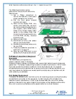
The DVM PCB’s electronics use a high input impedance voltage sense circuit. This
circuit draws very little current, while measuring the DC voltage drop across the
resistance under test. The AMPTEC 620LK main PCB slides in easily, by following
grooves on the inside of the aluminum case.
Schematics for the 620LK’s PCB are protected and strictly confidential, regardless of
the circumstance.
E-4 Block Diagram and Circuit Description
E-5 Principle of Operation
Using Ohm's Law (V/I =R), the AMPTEC 620LK Bond Meter first outputs constant DC
current through a given test resistance, then measures the voltage drop
across it while
scaling its display as resistance. The 1.9999
Ω
range outputs a constant 100 mA DC
l
evel of test current. On a 1 Ω
resistor, the 620LK 100mA output should get a 100mV
drop (0.10V/0.10A). For DVM scaling on the 2
Ω
range, voltage drop is amplified using a
x10 (for range scaling), hence a 10 mV drop becomes 100mV. This DVM input is
displayed as 100.00 m
Ω
on a 0.100
Ω
std. During the cycle, the meter changes
polarity, samples again, and displays the average reading of both polarities.
E-6 PCB Troubleshooting and Diagnostic Testing
If the malfunction is a faulty part, the repair of the 620LK meter can be attained by
replacing the proper internal PCB. There are no serviceable components (much of the
components are surface mount) on the 620LK PCBs, so it is often a case of entire PCB
replacement. See section E-2 on page 13 for more information about sending your
product in for repair.
The following sub-sections will facilitate the diagnosis as to whether the AMPTEC
620LK current source circuitry or digital voltmeter circuitry needs repair or replacement.
These steps should only be performed by authorized personnel who are trained to do
so.


