


33
Electric Actuator
OMMG00012
Rev 12 – NOV 2019
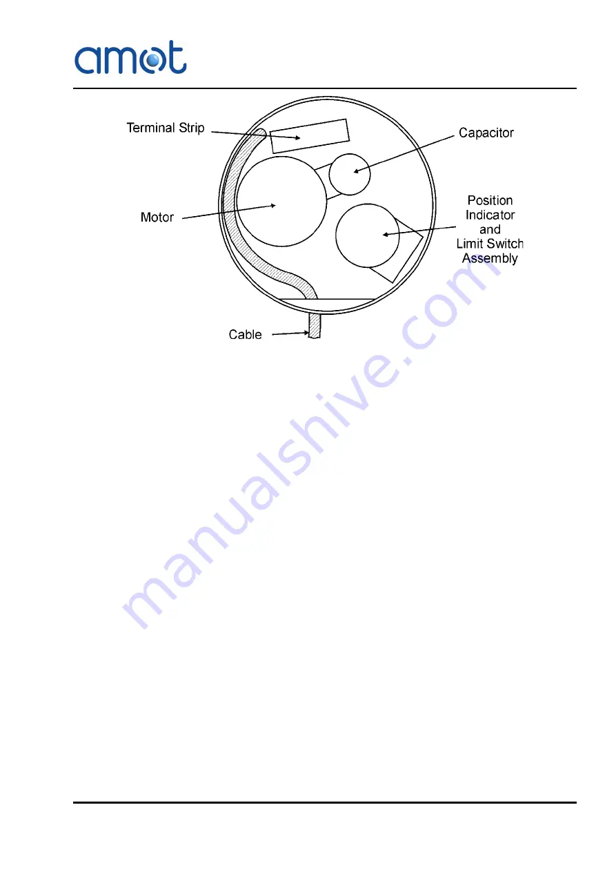
Fig 11
Actuator Internal Cable Routing
Electrically connect the actuator in accordance with the system wiring
diagrams in Section 7 (System Integration). Schedule a periodic maintenance
check to ensure proper performance and long service life. It is recommended
that the actuator is checked for correct operation at least once per month.
Note
The terminal strip employs spring loaded connections. Apply pressure to
the top of the terminal with a small, flat blade screwdriver to open the
connector. Insert the wire and release the pressure on the screwdriver.
The wire is then held in the connector by the spring.
4.5.1
Electrical Position Feedback
A potentiometer is fitted as standard, to all versions of the EA actuator. Where
a Positioner is also fitted, the Positioner uses the potentiometer to determine
the position of the actuator. With a Positioner fitted, 5V dc is applied across
the track connections of the potentiometer, giving a voltage out of the wiper
contact. This voltage is fed into the Positioner, but may also be used to give
an external position indication, provided that the signal is not loaded
significantly. An impedance to 0V of not less than 100k ohms is
recommended.
When no Positioner is fitted, the three potentiometer terminals are not
electrically connected to anything in the actuator, and may be used with any
external circuit to give position indication.
The potentiometer is geared to the actuator output shaft such that it rotates
about 270 degrees for a full quarter turn of the valve. This means that the
wiper contact of the potentiometer will never get fully to either end of the
potentiometer track.
Содержание 10GEF
Страница 1: ...Doc No OMMG00012 Revision 12 NOV 2019 G Valve electric actuator Operation and Maintenance Manual...
Страница 2: ......
Страница 14: ...14 System Overview Rev 12 NOV 2019 OMMG00012...
Страница 26: ...26 Electric Actuator Rev 12 NOV 2019 OMMG00012 Fig 7 EA Actuator Internal Wiring Without Positioner...
Страница 28: ...28 Electric Actuator Rev 12 NOV 2019 OMMG00012 Fig 9 EA Actuator Internal Wiring With Positioner...
Страница 52: ...52 Electric Actuator Rev 12 NOV 2019 OMMG00012...
Страница 54: ...54 PID Controller Rev 12 NOV 2019 OMMG00012...
Страница 64: ...64 System Integration Rev 12 NOV 2019 OMMG00012 Fig 22 System Wiring Diagram 8072D Controller...
Страница 67: ...67 System Integration OMMG00012 Rev 12 NOV 2019...
Страница 68: ...68 System Integration Rev 12 NOV 2019 OMMG00012...
Страница 74: ...74 Technical Data Rev 12 NOV 2019 OMMG00012 9 1 1 Valve Bore Fig 25 Valve Selection Curve...