17
3. 380V Wire connection and circuit diagram
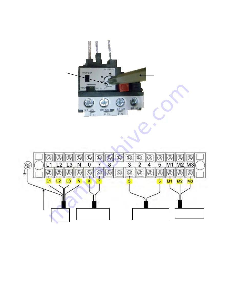
3.1 Wire connection diagram in the control box
(See Fig. 26)
.
3.2 380V Wire connection diagram of hydraulic motor
(See Fig. 27)
.
Motor wire (M1
、
M2
、
M3) are connected to the three wires in the motor.
Turn on the power, push
UP
button, if motor run but lift does not work, please
change the wires connection.
This point shows
the present rated
current value
Using cross screwdriver
to adjust rated current
value of thermal relay
Fig. 25
Power
wire
Wire of hydraulic
solenoid valve
Wire
of limit switch
Wire of motor
Fig. 26
Earth wire
Содержание A240
Страница 1: ...TWO POST LIFT Model A240 ...
Страница 4: ...2 Arm Swings View 2513mm 1270mm 814mm 683mm 1159mm Fig 2 ...
Страница 11: ...9 2 Install cables See Fig 14 Fig 14 ...
Страница 12: ...10 F Assembly oil hose assy 1 Install oil hose See Fig 15 Fig 15 81 85 81A 81 79A 80 81 81 79 ...
Страница 26: ...24 IV EXPLODED VIEW Model A240 Fig 38 Car in direction ...
Страница 27: ...25 Cylinders Control Box Fig 39 Fig 40 ...
Страница 40: ... 38 72225302 01 2014 ...


