Seite 18 von 19
AMG Sicherheitstechnik GmbH
Industrial Park Road A-9
39245 Gommern
Phone 039200-7797-0
Freecall 0800-2264264*
Fax 039200-7797-29
www.amg-sicherheitstechnik.de
Business hours are 8-17 clock, outside this time an answering machine is switched
*) free of charge from the German fixed network and all German mobile networks
spark
gap
During commissioning, the most important task is to choose a suitable position for
transmitter and receiver.
If you are not satisfied with the picture quality, select a different position for the
transmitter or the receiver if you move the device / antenna of the transmitter or
receiver 3-5 cm to the right or left or up and down, sometimes making small changes
great difference and improvement in reception.
Also, the position of the antennas can improve or degrade the reception quality. Test the
antennas vertically, diagonally or horizontally and check the received image.
In addition, you can gradually reduce the distance between transmitter and receiver. If
you now get the desired result, you can now see which wall e.g. shields so strongly that
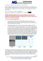
a wireless connection is impossible. Transmitter and receiver use so-called
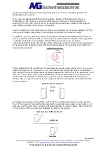
omnidirectional rod antennas. Ideally, these antennas send and receive their signal like a
circle around the antenna (horizontal 360 degree signals). The practice looks different,
however (see picture).
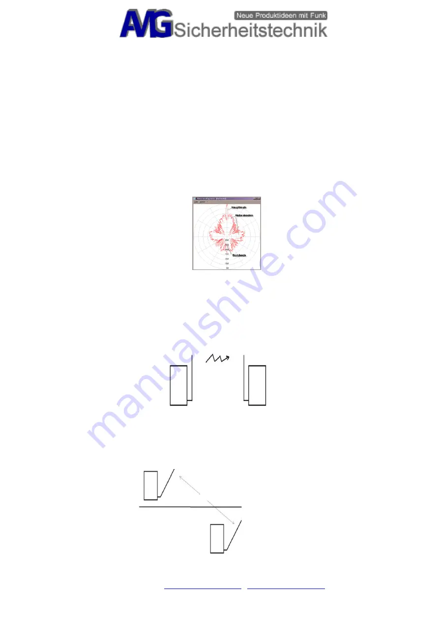
These signals then hit on different dense materials (walls, water pipes, etc.). If you now
flatten the antenna of the receiver, then the transmitter signals go over it. Transmitter
and receiver Antennas must always be aligned parallel to each other (see diagrams), as if
they are next to each other, just separated by rooms. If the receiver now receives the
signals, then it depends on whether the receiver in the "radio shadow" behind e.g. a
thicker wall or a pipe or electric line is located. This is the procedure when both devices
are on one level.
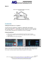
Let's take the example, transmitter on the 1st floor, diagonally below it on the ground
floor of the receiver. Now both antennas must be aligned at an angle to each other, as if
they are next to each other / stand, just separated by the ceiling. Again, then 30-50 cm
to the right or left to avoid radio shadows by steel in the ceiling.
Antennas are at different levels
Receiver
spark gap
Antennas are on one level

