background image


23 


System Service and Maintenance Periods


Check Victaulic  

Connections for Leaks 

Clean Condenser  

Filters 

Torque All Screw 

Type Connections 

(refer to torque 

User Interface to Fill Out 

the Service Schedule 

Содержание CHILLBATCH AMC-20

Страница 1: ...uires specific knowledge and training Improperly installed adjusted or altered equipment by and unqualified person could result in death or serious injury When working on the equipment observe all pre...

Страница 2: ...bel ELECTRICAL SHOCK HAZARD Failure to do so can result in improper oil distribution in compressors and will terminate factory warranty Anchor bolts must be used in the provided locations on each of t...

Страница 3: ...alies or acids If so has the condenser been coated to protect against degradation The proper precautions have been taken before turning on the chiller INSTALLATION NOTES ______________________________...

Страница 4: ...ndenser fans for optimal efficiency and head pressure control statically and dynamically balanced Independent master control modules can function independently by simply turning a switch System run an...

Страница 5: ...ton compressors While both are single refrigeration circuits the 30 ton module has the capability of unloading a compressor and changing its minimum step capacity to roughly half In some instances whe...

Страница 6: ...ge between 20 120 Tons in 10 ton increments by pairing various 20 and 30 ton modules together For example a 70 ton bank consists of 1 30 ton and 2 20 ton modules The pump size for this configuration i...

Страница 7: ...6 Product Information Table 1 Physical Data 20 60 Ton Units...

Страница 8: ...7 Product Information Table 2 Physical Data 70 120 Ton Units...

Страница 9: ...8 Physical Dimensions 20 30 Ton Units...

Страница 10: ...9 Fig 1 ECM 10 12 xxxxxA 10 12 5 Ton Units Physical Dimensions 40 50 60 Ton Units...

Страница 11: ...10 Physical Dimensions 70 80 90 Ton Units...

Страница 12: ...11 Physical Dimensions 100 110 120 Ton Units...

Страница 13: ...12 Fork Lifting...

Страница 14: ...13 Lifting Via Crane...

Страница 15: ...14 Lifting Via Crane Cont...

Страница 16: ...15 Chiller Installation and Clearances...

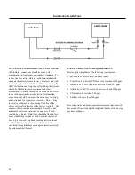
Страница 17: ...n of the bulk head connector Under no circumstances should the tank temperature sensor be removed during operation this will result in compressor short cycling and could damage critical components of...

Страница 18: ...e Transducer 0 100psig This sensor measures the dynamic conditions related to the entering fluid pressure pump discharge pressure and is responsible for measuring restrictions in the fluid circuit Thi...

Страница 19: ...ture From the Home Screen page locate the pump info using the down arrow Record the pump pressure displayed on the display verify that the pump is in fact running via the over ride or the physical pum...

Страница 20: ...Turn the Operation Switch located on the master control box into the on position the fluid pump should then begin flowing fluid throughout the fluid circuit To confirm fluid flow press the down arrow...

Страница 21: ...Temp protection limit Refrigerant Suction Temp Refrigerant Discharge Pressure ratio metric sensor Refrigerant Suction Pressure ratio metric sensor Refrigerant Super Heat Module 4 Control Module 1 Cont...

Страница 22: ...ry warranty All strainers should contain at minimum a 30 mesh count and must be serviced biannually or quarterly if water conditions are harsh Fluid lines should be flushed for 6 hours without any res...

Страница 23: ...pull exceeds 100 ft Table 3 shall not be used to select wire Proper voltage drop calculation should be considered and the wire size must be adjusted per the adjusted ampere rating Electrical Installa...

Страница 24: ...3 System Service and Maintenance Periods Check Victaulic Connections for Leaks Clean Condenser Filters Torque All Screw Type Connections refer to torque User Interface to Fill Out the Service Schedule...

Страница 25: ...24 System Service and Maintenance Periods Cont...

Страница 26: ...ain plug 3 location and a second line extending from the container to the top header drain plug 2 location Replace the plug on the pump head before circulating the fluid mixture 4 When the pump begins...

Страница 27: ...26 Winterizing Freeze Protection Cont...

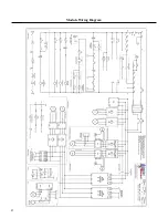
Страница 28: ...27 Module Wiring Diagram...

Страница 29: ...28 Module Panel Layout...

Страница 30: ...which have been returned to the manufacturer The Company shall not be obligated to pay for the cost of lost refrigerant No liability whatever shall attach to the Company until said products have been...

Страница 31: ......

Страница 32: ...1037 Old Salem Road Murfreesboro TN 37127 Phone 615 890 6985 info amgeo com www amgeo com...

Отзывы: