17
Table 1 - EAC, Air Cooled Chiller Physical Data
Equipment Operation and Controls Overview Cont.
Trans A Alarm” will require a physical reset by
pressing and holding the caution symbol on the c.Pco
control.
d.
Hight Pressure Ratiometric Transducer (0-650
psig range)
- This pressure transducer is designed to
measure and display dynamic conditions of the
compressors discharge line. In addition, the
condenser fan speed is controlled by this transducer
and has a factor setting to maintain 450 psig at the
discharge line.. Default cut in/out values are 550/600
psig respectively
(Dis A Trans Alarm)
and can trip 3
times within 1 hour before locking out the
compressor.
CONDENSER PROTECTION
FILTERS
- If the equipment contains condenser
filters and repetitive high pressure conditions are
observed, check the filters and clean as often as
necessary. Dirty filters will result in continued high
refrigerant pressure conditions and can damage
equipment if periodic maintenance is not maintained.
Refer to the maintenance and trouble shooting
sections of this manual for more details.
e. Fluid Out Temperature Sensor (NTC) -
This sensor
measures the dynamic temperature of the fluid leaving
each module. It can be located on back of the chiller
between the isolation valve and the evaporator - black
cable recessing into the insulation. The default fluid
out temperature cut in/out is 32.5/38
°
F and with
continue to cycle with out limitation. However, if the
fluid temperature suppresses below 32.2
°
F, the unit
will lock out and require a physical reset by pressing
and holding the caution symbol on the c.pco. control.
If continued low temperature conditions are observed,
check the fluid y-strainer and ensure fluid flow of the
fluid circuit. Refer to the maintenance and trouble
shooting sections of this manual for more details on
low flow conditions and how they consequently affect
the equipment.
f. Suction Temperature Sensor (NTC)
- This devise
is responsible for measuring the refrigerant suction
temperature. This sensor is also key in deriving the
Super Heat reading on the user interface. Note: The
displayed Super Heat reading should never be used to
set refrigerant change or service the unit in any way.
Note: The suction temperature sensor should be
wrapped in cork tape to and insulated to function
correctly.
g. Entering Fluid Pressure Transducer (0-100psig.) -
This sensor measures the dynamic conditions related
to the entering fluid pressure (pump discharge
pressure) and is responsible for measuring restrictions
in the fluid circuit. This parameter contains read/write
functionality in which must be set by the user per the
installation conditions. For example, we expect the
fluid pressure of a system to less when installed on a
8’ diameter horizontal tank as opposed to a 27’ tall
vertical tank. Considering this, the factory will deliver
the equipment with its run tested operation conditions
however, the user will be required to set this parameter
during installation. Please refer to the start up section
of this manual on setting the pump pressure setpoints.
CHILLER START UP AND OPERATION
WARNING— The system start up should be performed by
an certified individual whom contains the appropriate
knowledge of chillers and air conditioning equipment.
Damage to the equipment caused by negligent installation
and/or, equipment operation will not be covered under the
manufactures warranty.
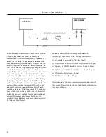
a. Line Voltage Connection,
refer to the “Electrical
Installation and Wire Sizing Guide” for details on wire
sizing and connecting line voltage. All overcurrent
protection (fuses) should be class R with the
appropriate voltage and current ratings.
b. Tank Temperature Sensor Connection,
the tank
temperature sensor must be installed in the fluid tank
closest to the chiller supply connection. If installing
the tank temperature sensor inside the tank is not
possible and with the consent of American
GeoThermal, the sensor can be installed in the chiller
supply line. When doing so, the chiller must be
activated to “continuous pump mode” via the c.pco
control. Failing to do so can result in damage to the
equipment and will nullify the manufactures warranty.
c.
Chiller Plumbing,
refer to Table 1 & 2 for standard
chiller connection sizes and minimum line sizes for a
50 ft run. This line size does not account for
additional 90
°
elbow and should only be used for
flexible hose. Consult with American GeoThermal if
additional elbows are required for piping, standard
equipment pumps may not be applicable for said
application.
d.
12 Hour Warming Period,
All units come equipped
with a crankcase heaters, furnish power to heater a
minimum of 12 hrs. before starting unit. To apply
power to the heater only, set low voltage breaker
(CB6) to off and the compressor breakers (CB1 and
CB2) to the on positions. Close all cabinet covers
during the waiting period to prevent burns or electrical
Содержание CHILLBATCH AMC-20
Страница 7: ...6 Product Information Table 1 Physical Data 20 60 Ton Units...
Страница 8: ...7 Product Information Table 2 Physical Data 70 120 Ton Units...
Страница 9: ...8 Physical Dimensions 20 30 Ton Units...
Страница 10: ...9 Fig 1 ECM 10 12 xxxxxA 10 12 5 Ton Units Physical Dimensions 40 50 60 Ton Units...
Страница 11: ...10 Physical Dimensions 70 80 90 Ton Units...
Страница 12: ...11 Physical Dimensions 100 110 120 Ton Units...
Страница 13: ...12 Fork Lifting...
Страница 14: ...13 Lifting Via Crane...
Страница 15: ...14 Lifting Via Crane Cont...
Страница 16: ...15 Chiller Installation and Clearances...
Страница 25: ...24 System Service and Maintenance Periods Cont...
Страница 27: ...26 Winterizing Freeze Protection Cont...
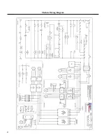
Страница 28: ...27 Module Wiring Diagram...
Страница 29: ...28 Module Panel Layout...
Страница 31: ......
Страница 32: ...1037 Old Salem Road Murfreesboro TN 37127 Phone 615 890 6985 info amgeo com www amgeo com...


