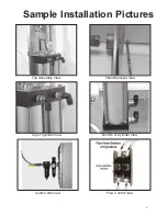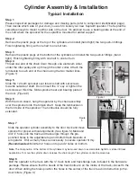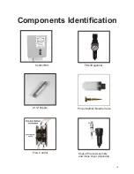
Cylinder Assembly & Installation
Typical Installation
Step 1
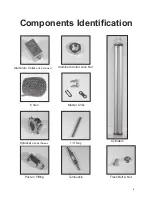
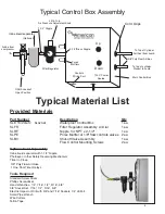
Please inspect all packages for damage and missing parts (refer to component identification page).
Then decide which side of your door you wish to install your new Supralift operator
.
The Supralift
is
versatile enough to mount to either side of the door.
It's advised to use a bearing plate at the end of
the shaft where the sprocket for the supralift is mounted for added support.
Step 2
Remove the plastic plugs at the top of the cylinders and install (hand tight) the two push-in fittings.
Finish tightening
firmly
with one half to one full turn
Step 3
Remove the plastic plugs at the bottom of the cylinders and install the two push-in fittings (hand
tight).
Finish tightening
firmly
with one half to one full turn
Step 4
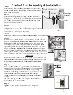
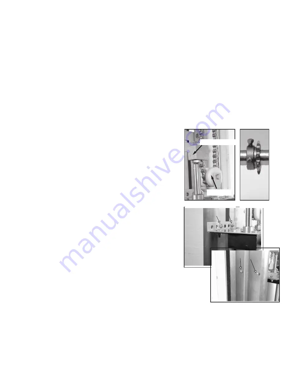
Thread one end of the chain down through one aluminum collar
under the idler pulley and up through the other collar.
Attach the
turnbuckle to each end of the chain using the two master links.
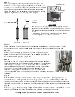
(Figure 1)
Step 5
Slide the 12 tooth sprocket over torsion shaft with set screws
towards outside of shaft.
Do not insert the ¼" key or tighten the
set screws at this time.
Slide sprocket near end bearing plate of
the door.
(Figure 2)
Step 6
With the door closed, hang the operator by the chain assembly
over the sprocket onto the torsion shaft.
Keep the turnbuckle on
the front side of the sprocket.
7KHWXUQEXFNOHVKRXOGEHIXOO\
H[WHQGHG
Step 7
Slide the operator cylinder assembly to the door track and move
sprocket for proper vertical alignments. (See figure 5) Mark and
drill ¼" holes into the track and track angle through the pre-
punched holes in the adjustable top and bottom track brackets of
air operator. Drill as many holes as necessary to secure operator firmly.
(
Recommended:
Minimum 2 holes on top and 2 holes on bottom.
Note:
The final position of the bottom of the cylinders may be moved down to accommidate highlift or vertical lift track
applications.
To move the cylinder down increase the chain length.
The cylinders cannot be moved up.
Step 8
Bolt the operator to the track with the ¼" track bolts and track flange nuts included in the hardware
package.
Please ensure that the heads of the track bolts are on the inside of the track, closest to the
door.
When drilling the holes position the holes in the center of the track to avoid obstruction to the
door rollers. (Figure 3)
Figure 1
Figure 2
Idler Pulley
Aluminum Collar
Figure
3
Track Nuts
Track Bolts
7
Содержание Supralift II
Страница 1: ...Air Powered Operator Installation Manual 1 1 2020 American Garage Door Supply Inc 1 800 233 1487 1...
Страница 17: ...17...
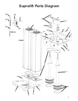
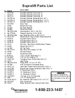
Страница 18: ...1 2 3 4 5 6 7 8 9 10 11 12 13 8 14 5 7 9 15 16 17 18 19 20 21 22 23 24 27 25 26 28 Supralift Parts Diagram 18...
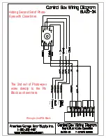
Страница 20: ...Photo Eye Base Black White Black White Black Receiver White Black White Transmitter 20...
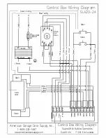
Страница 22: ...Control Box Wiring Diagram 1 800 233 1487 Old Style 22...


