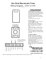
One Shot Macromatic Timer
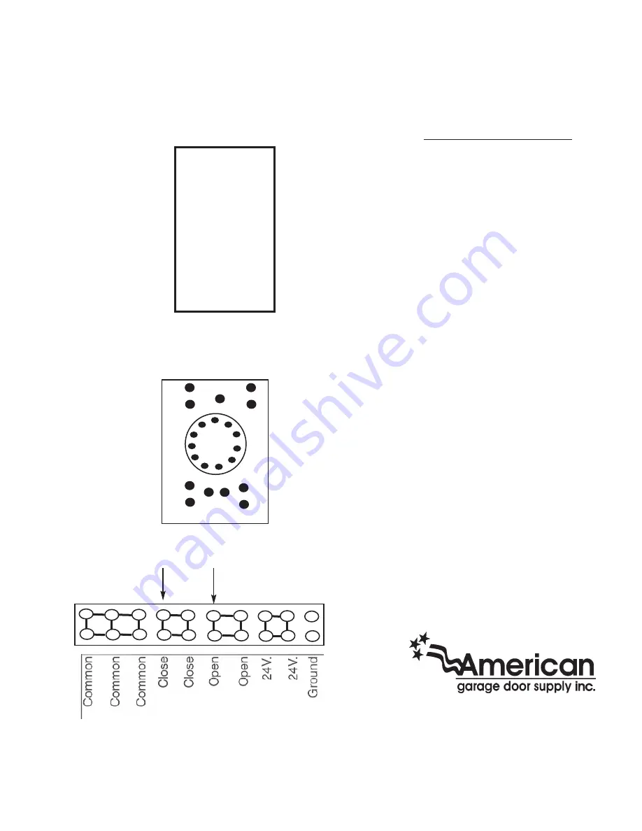
Wiring Diagram - 120 V or 24V
10-11-07
7
6
5
Note:
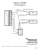
This wiring Diagram is set up for Supralift & NuMax Air-Powered Operators only.
# 3
# 1
1-800-233-1487
www.carwashdoors.com
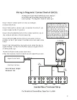
Wiring Contact Block
1. Primary Power to the Unit-
The Macromatic Time Delay Relay requires
power at all times to power the unit. Wire pri-
mary power to the unit by connecting #2 and
# 10 to the correct power source.
For 120VAC one shot timers use 120VAC
(Polarity not important) or 120VDC (Polarity
is important)
Use the same rules for 24volt timer.
2. Power Trigger-
The power trigger is the input into the timer
from your equipment or other
electrical accessory that is triggering the
timer to work. Use 5 and 7 on the contact
block for connection to your incoming
signal.
This signal should be a continuous signal
with the same voltage as the timer primary
power.
For 120VAC one shot timers use 120VAC
(Polarity not important) or 120VDC (Polarity
is important) Again for 24 Volt timers use the
same rules.
2. Output to Opener-
Wire the contact block to your opener.
Terminals 1 and 3 are normally open and 1
and 4 are normally closed. In most cases
use 1 and 3. Wire 1 and 3 to the common
and open or closed (dependent upon the
functionality you require.
Note: Other N.O and N.C contacts are avail-
able for multifunctionality and
operate at the same time as the former men-
tioned terminals. N.C is 11 and 8 and N.O is
11 and 9.
One Shot Timer
9
4
9
11
10
1
Macromatic
Contact Block
11 Pin Socket
3
2
This is an example of a
open signal. For Close,
wire #3 to Close.
26
Содержание Supralift II
Страница 1: ...Air Powered Operator Installation Manual 1 1 2020 American Garage Door Supply Inc 1 800 233 1487 1...
Страница 17: ...17...
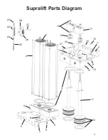
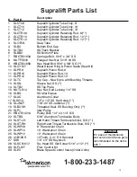
Страница 18: ...1 2 3 4 5 6 7 8 9 10 11 12 13 8 14 5 7 9 15 16 17 18 19 20 21 22 23 24 27 25 26 28 Supralift Parts Diagram 18...
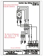
Страница 20: ...Photo Eye Base Black White Black White Black Receiver White Black White Transmitter 20...
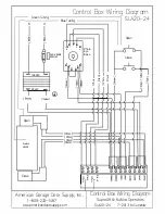
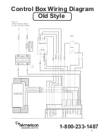
Страница 22: ...Control Box Wiring Diagram 1 800 233 1487 Old Style 22...

