Step 1
Step 5
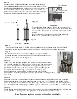
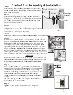
Open the cover of the control box and connect two 3/8” polyflow
lines to the two push-in fittings on the valve inside the control box.
Plumb through the cord grips located on the right side of the
control box to the push-in fittings located on the top side of the
operator cylinders. Plumb the airlines from the control box to the
top of the operator cylinders. The top airline fitting on the control
box goes to the front cylinder (farthest from the jamb) and bottom
airline goes to the back cylinder (closest to the jamb). Tighten cord
grips on the right side of the control box when complete. (Figure 2)
Important!
Control boxes should be used with an inline
OLTXLGVHSDUDWRU
!! See
recommendations.
We recommended to keep the airlines as short
as possible to reduce internal condensation in the airlines
Step 6
0RXQW
the flow control kit to your wall.
It is recommended to
locate the flow control kit in an area away from the doorway
and direct spray.
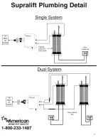
Plumb 3/8”
airlines from the previously
installed push-in fitting on the bottom of the cylinders to the
push-in fittings located on the top of the flow controls.
Plumb the line from cylinder nearest the jamb to the close
and the
line farthest away from the jamb to open.
Plumb bottom of
flow control with a 12”
drain tube
Step 7
Tighten the flow control
YDOYHV
(clockwise) completely.
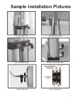
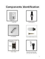
Figure 1
Filter/Regulator
Shut-off Valve Assembly
2-1/2” Nipple
Valve
Airlines
Cord Grips
Figure 2
Figure 3
Figure 4
Control Box Assembly & Installation
To
Cylinders
From
Compressor
Push-in Fittings
To Flow
Control
Install the two
3
orex mufflers
RU)ORZFRQWUROYDOYHV
to the top and bottom ports
on the left side of the control
box.
Hand tighten only.
Step 2
Install the filter regulator assembly onto the control box
using the 2½" brass nipple.
Insert through the middle hole
on the left side of the control box and tighten.
Use teflon
tape on threads.
(Figure 1)
Step 3
Install the shut-off valve assembly into the filter/regulator
using the 1-1/2”
QLSSOH
For optional inline
OLTXLGVHSDUDWRU
use additional 1-1/2”
nipple.
(Figure 1)
Step 4
Mount the control box to the wall or other surface at the desired location .
O
ptional Inline
D
ryer/
S
eparator
11
Содержание Supralift II
Страница 1: ...Air Powered Operator Installation Manual 1 1 2020 American Garage Door Supply Inc 1 800 233 1487 1...
Страница 17: ...17...
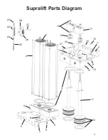
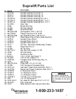
Страница 18: ...1 2 3 4 5 6 7 8 9 10 11 12 13 8 14 5 7 9 15 16 17 18 19 20 21 22 23 24 27 25 26 28 Supralift Parts Diagram 18...
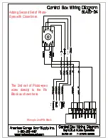
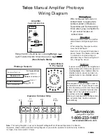
Страница 20: ...Photo Eye Base Black White Black White Black Receiver White Black White Transmitter 20...
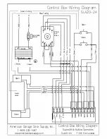
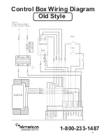
Страница 22: ...Control Box Wiring Diagram 1 800 233 1487 Old Style 22...


