Quick Setup Guide
3
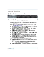
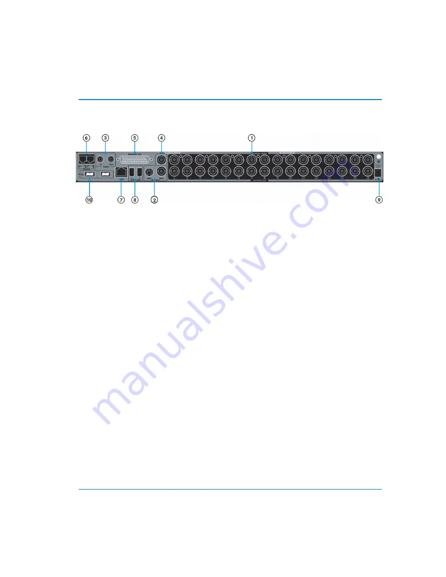
CONNECTING YOUR DIGIMUX
WARNING: POWER SHOULD BE OFF BEFORE MAKING ANY CONNECTIONS
TO THE UNIT.
NOTE: For further details regarding installation and connections, see the
DigiMux User’s Manual
.
1. Video Inputs:
Connect the video signal from each camera to one of the
video input BNC connectors marked
Video In
.
2. Main Monitor Out:
Connect the Main Monitor to the
Main Monitor
Output
of the unit (either BNC or S-VHS connector).
3. Audio In/Out:
Connect any amplified audio devices (microphone,
speakers) to the audio I/O ports (optional).
4. Call Monitor Out:
Connect the Call Monitor to the
Call Monitor Output
BNC connector (optional).
5. External I/O Board:
Connect any external alarm devices and dome
cameras to the External I/O board and connect the board to the unit.
6. RJ-11 RS-485 Port:
Connect an RS-485 remote keyboard, such as a
ControlCenter 200 or 300 keyboard.
NOTE: The RJ-11 port is not for use with a telephone line.
7. Ethernet Connection:
Connect the Ethernet cable for remote network
access.
NOTE: The default IP address must be changed in order to avoid
conflicts with other units on the network.
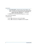
8. IEEE-1394 HDD Firewire:
For expansion with external storage modules.
Figure 3 — DigiMux Connections
Содержание DigiMux DG4004
Страница 8: ...Quick Setup Guide viii NOTES ...


