background image

113345-9


www.amdry.com

5

!

!

!

!

Unpacking/Setting Up _________________

Remove protective shipping material (i.e., plastic wrap, and/
or optional shipping box) from dryer.

Important

Dryer must be transported and handled in an upright

position at all times.

The dryer can be moved to its final location while still attached
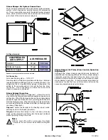
to the skid or with the skid removed.  To unskid the dryer,
locate and remove the four (4) bolts securing the base of the
dryer to the wooden skid.  Two (2) are at the rear base (remove
the back panel for access), and two (2) are located in the
bottom of the lint chamber.  To remove the two (2) bolts located
in the lint chamber area, remove the lint door.

With the skid removed, to make it easier to slide the dryer into
its final position, slightly lower all four (4) leveling legs, so
that the dryer will slide on the legs instead of the base frame.

The lint coops of all dryers are supported during shipping by
a bracket.  Remove this bracket before starting the dryer.

Leveling Dryer

The dryer is equipped with four (4) leveling legs, one (1) at
each corner of the base.  Two (2) are located at the rear of the
dryer base, and two (2) are located in the lint chamber (coop).
To increase bearing life and improve efficiency, the dryer
should be tilted slightly to the rear.

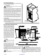
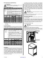
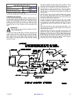
Bulkheads and partitions should be
made of noncombustible materials
and must be located a minimum of
12-inches (30.48 cm) (18-inches
[45.72 cm] or more is recommended
f o r   e a s e   o f   i n s t a l l a t i o n ,
maintenance, and service) above
the dryer outer top, except along the
front of the dryer which may be
partially closed in if desired.  The
clearance between the bulkhead
header and the dryer must be a
minimum of 4-inches (10.16 cm) and
must not extend more than 4-inches
(10.16 cm) to the rear of the front.
The bulkhead facing must not be
closed in all the way to the top of the
dryer.  A 1-inch (2.54 cm) clearance
is required.

Note

Allowances must be made

for opening the control
door.

Dryers may be positioned sidewall
to sidewall.  However, a 1/16” (1.58
mm) minimum allowance must be
made for the opening and closing of
the control door and the lint door.  It

Important

When fire sprinkler systems are located above the

dryers, a minimum of 18-inches (45.72 cm) above
the dryer console (module) is required.  Dryers may

be positioned sidewall to sidewall however, a 1/16” (1.58 mm)
minimum allowance is required between dryers (or wall) for
ease of installation and maintenance.  Allowances must be
made for the opening and closing of the control door and the
lint door.

Dryer Enclosure Requirements________

is suggested that the dryer be positioned about 2 feet (0.61
meters) away from the nearest obstruction for ease of
installation, maintenance, and service (to be measured from
the back guard).  Refer to the illustration above for details.

Note

Air considerations are important for proper and
efficient operation.

Содержание ML-55 Phase 7

Страница 1: ...plier call the fire department Installation and service must be performed by a qualified installer service agency or the gas supplier Avertissement Assurez vous de bien suivre les instructions données dans cette notice pour réduire au minimum le risque d incendie ou d explosion ou pour éviter tout dommage matériel toute blessure ou la mort Ne pas entreposer ni utiliser d essence ni d autres vapeur...

Страница 2: ...at 508 678 9000 Please specify the dryer model number and serial number in addition to the description and part number so that your order is processed accurately and promptly Important Note To Purchaser Information must be obtained from your local gas supplier on the instructions to be followed if the user smells gas These instructions must be posted in a prominent location near the dryer Retain T...

Страница 3: ...rve all safety precautions displayed on the equipment and or specified in the installation manual included with the dryer Dryer must be installed in a location environment which the ambient temperature remains between 40 F 4 44 C and 130 F 54 44 C Caution Label all wires prior to disconnection when servicing controls Wiring errors can cause improper operation Attention Au moment de l entretien des...

Страница 4: ...m experience at each location Warning The collection of lint in the burner area and exhaust ductwork can create a potential fire hazard For personal safety the dryer must be electrically grounded in accordance with local codes and or the National Electrical Code ANSI NFPA NO 70 LATEST EDITION or in Canada the Canadian Electrical Codes Parts 1 2 CSA C22 1 1990 or LATEST EDITION Note Failure to elec...

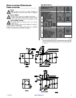
Страница 5: ...AIR VOLUME 0 75 cfh 0 02 cmh BOILER HP NORMAL LOAD 4 2 Bhp SUPPLY CONNECTION 1 F N P T RETURN CONNECTION 1 F N P T Specifications _________________________ Shaded areas are stated in metric equivalents 12 01 04 Specify air operated steam damper system or electromechanical steam damper system when ordering Air operated steam damper system must be provided with a clean dry regulated 80 psi 10 psi 5 ...

Страница 6: ... Fuel Gas Code ANSI Z223 1 LATEST EDITION or in Canada the installation must conform to applicable Canadian Standards CAN CGA B149 1 M91 Natural Gas or CAN CGA B149 2 M91 L P Gas or LATEST EDITION for General Installation and Gas Plumbing The dryer must be installed on a sound level floor capable of supporting its weight Carpeting must be removed from the floor area that the dryer is to rest on Im...

Страница 7: ...erials and must be located a minimum of 12 inches 30 48 cm 18 inches 45 72 cm or more is recommended for ease of installation maintenance and service above the dryer outer top except along the front of the dryer which may be partially closed in if desired The clearance between the bulkhead header and the dryer must be a minimum of 4 inches 10 16 cm and must not extend more than 4 inches 10 16 cm t...

Страница 8: ..._______ When the dryer is operating it draws in room air heats it passes this air through the basket tumbler and exhausts it out of the building Therefore the room air must be continually replenished from the outdoors If the make up air is inadequate drying time and drying efficiency will be adversely affected Ignition problems and sail switch fluttering problems may result as well as premature mo...

Страница 9: ... 6 meters The minimum diameter of this ductwork must be at least 8 inches 20 32 cm In the case of multiple common dryer venting the distance from the last dryer to the outside exhaust outlet must not exceed 15 feet 4 6 meters The shape of the ductwork is not critical as long as the minimum cross sectional area is provided It is suggested that the use of 90º turns be avoided use 30º and or 45º angl...

Страница 10: ...ections must be made by a properly licensed and competent electrician This is to ensure that the electrical installation is adequate and conforms to local and state regulations or codes In the absence of such codes all electrical connections materials and workmanship must conform to the applicable requirements of the National Electrical Code ANSI NFPA NO 70 LATEST EDITION or in Canada the Canadian...

Страница 11: ...ng A ground earth connection must be provided and installed in accordance with state and local codes In the absence of these codes grounding must conform to applicable requirements of the National Electrical Code ANSI NFPA NO 70 LATEST EDITION or in Canada the installation must conform to applicable Canada Standards Canadian Electrical Codes Parts 1 2 CSA C22 1 1990 or LATEST EDITION The ground co...

Страница 12: ...copper lug also provided in this box To gain access the service box cover must be removed The neutral will only be used on 4 wire service This is typical for 380 416V 50 Hz Electrically Heated Models Only The only electrical input connections to the dryer are the 3 phase 3ø power leads L1 L2 L3 and sometimes neutral and ground Single phase 1ø power for the control circuit and for any single phase ...

Страница 13: ...e ANSI Z223 1 LATEST EDITION or in Canada the Canadian Installation Codes CAN CGA B149 1 M91 Natural Gas or CAN CGA B149 2 M91 L P Gas or LATEST EDITION as well as local codes and ordinances and must be done by a qualified professional Note Undersized gas piping will result in ignition problems slow drying increased use of energy and can create a safety hazard The dryer must be connected to the ty...

Страница 14: ...re exceeds 12 0 inches 29 9 mb of water column pressure W C Note A water column W C test pressure of 3 5 inches 8 7 mb for natural gas and 10 5 inches 26 1 mb for liquid propane L P dryers is required at the gas valve pressure tap of each dryer for proper and safe operation A 1 8 N P T plugged tap accessible for a test gauge connection must be installed in the main gas supply line immediately upst...

Страница 15: ...m riser along with a drip trap and check valve This will prevent any condensate from entering the steam coil Flexible hoses or couplings must be used The dryer vibrates slightly when it runs and this will cause the steam coil connections to crack if they are hard piped to the supply and return mains Shutoff valves for each dryer should be installed in the supply line return line and drip trap retu...

Страница 16: ...ed in metric equivalents Air Connection Air connection to system 1 8 N P T No air regulator or filtration is provided with the dryer External regulation filtration of 80 psi 5 52 bar must be provided It is suggested that a regulator filter gauge arrangement be added to the compressed air line just before the dryer connection This is necessary to ensure that correct and clean air pressure is achiev...

Страница 17: ... module will lock out until it is manually reset To reset the ignition system open and close the main door and restart the dryer A gas pressure test should be taken at the gas valve pressure tap of each dryer to ensure that the water column W C pressure is correct and consistent Note Water column pressure requirements measured at the pressure tap of the gas valve body Natural Gas 3 5 Inches 8 7 mb...

Страница 18: ...ion and start drying The dryer will then start I E blower basket tumbler and heat The L E D display will read MANUAL DRYING CYCLE D 00 00 MIN REMAIN Note Press and hold the Up Arrow to view the basket tumbler temperature at any time The dryer can be stopped at any time by pressing the Stop Clear O key at this time the dryer will go into a cycle pause If the Stop Clear O key is pressed again at thi...

Страница 19: ...7 Note When ordering replacement parts from the ADC reseller or the ADC factory be sure to give them the correct model number and serial number so that your parts order can be processed in an expeditious manner Returning Warranty Parts______________ All dryer or parts warranty claims or inquiries should be addressed to the ADC Warranty Parts Department To expedite processing the following procedur...

Страница 20: ...ing supply house 90 Days Remove lint from around basket tumbler drive motors and surrounding areas Remove lint from gas valve burner area with a dusting brush or vacuum cleaner attachment Clean any lint accumulation in and around both the blower and drive motor casing openings Note To prevent damage avoid cleaning and or touching ignitor flame probe assembly Every 6 Months Inspect and remove lint ...

Страница 21: ...e retries trials If the flame is not sensed at the end of the third retry trial inter purge period of 30 seconds the DSI module will Lock Out light emitting diode L E D diagnostic indicator flashes A steady L E D indicator indicates normal operation No L E D indicator indicates a power or an internal failure has occurred For Models with Fenwal Controls DSI Module 128937 _______________________ The...

Страница 22: ...et manually This hi temperature condition may be caused due to a restricted exhaust poor airflow or improper burner operation The location of the burner Hi Limit is on the right side of the burner box looking at the burner from the back of the dryer Warning Discontinue power to dryer before attempting to reset Hi Limit DATA LABEL INFORMATION ______ When contacting American Dryer Corporation certai...

Страница 23: ...onfused with 3 4 N P T The sealing of an NH connection is made with a washer opposed to the mating threads of an N P T assembly The two 2 thread designs are not compatible Important Flexible supply line coupling must be used Solenoid valve failure due to hard plumbing connections will void warranty It is recommended that a filter or strainer be installed in the water supply line FIRE SUPPRESSION S...

Страница 24: ..._ While the dryer is in an idle state or 20 seconds after the heat turns off the Phase 7 control monitors the thermistor probe located in the top of the basket tumbler chamber and records the minimum temperature If the minimum recorded thermistor probe temperature is greater than 120 F 48 C and the control detects a 50 rise in temperature this will be the trip point and the F S S routine will acti...

Страница 25: ... section F S S Diagnostics Messages __________ Open Thermistor Probe This message indicates that the F S S thermistor probe either is not connected or is damaged If this condition is detected the Phase 7 non coin control will immediately enter F S S DISABLED mode Shorted Thermistor Probe This message indicates that the F S S thermistor probe is damaged or the wiring is shorted If this condition is...

Страница 26: ...ADC 113345 9 12 01 04 6 ...

Отзывы: