21
The furnace control module energizes the humidifier
whenever the combustion blower is energized (if there
is an optional air cleaner on the system, the humidifier
is not energized until the air cleaner is energized). The
control module energizes the air cleaner whenever the
air circulation blower is energized.
Low Voltage Wiring
Low voltage wiring may enter through the right or left
side of the furnace. See Section II for hole locations.
Run the thermostat wires through either hole, up through
a grommet in the blower deck, and to the ignition control
module. (Figure 22)
CAUTION
To avoid possible equipment malfunc-
tion, be careful to route the low voltage
wires so as not to interfere with filter
removal or other maintenance.
Low voltage wires may then be connected to the termi-
nal strip as shown below.
Figure 22
Typical Field Wiring
(24 VAC Control Circuit)
A 40\/ transformer and auxiliary fan relay are built into
the furnace so that is may be used with most cooling
equipment.
Consult the wiring diagram for both 115V and 24V
wiring details. The wiring diagram is located inside the
blower compartment door.
Line Voltage Connection of Optional
Humidifier and Electronic Air Cleaner
The control module in this furnace is equipped with line
voltage accessory terminals to be used for controlling
the power to an optional field-supplied humidifier and/or
electronic air cleaner.
CAUTION
Label all wires prior to disconnection
when servicing controls, wiring errors
can cause improper and dangerous op-
eration. Verify proper operation after ser-
vicing.
Accessory Load Specifications
Air Cleaner: 1.0 Amp maximum at 120 VAC
Humidifier: 1.0 Amp maximum at 120 VAC
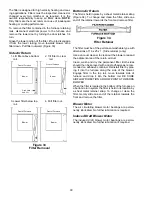
Accessory Installation
Follow the electronic air cleaner and humidifier manu-
facturers instructions for mounting and electrically
grounding these accessories. Check that the power
supply to the furnace has been disconnected. Wire the
accessories to the furnace control module as shown
below. All connections to the control module are to be
made through 1/4 (.250") receptacle (female) terminals.
If it is necessary for the installer to supply additional line
voltage wiring to the inside of the furnace, the wiring
must comply with all local codes. This wiring must have
a minimum temperature rating of 105° C and must be
routed away from the burner compartment. All line
voltage wire splices must be made inside the furnace
junction box.
Control Module
Coo
l
Hea
t
Pa
rk
Pa
rk
Li
ne
Tr
an
sfo
rm
er
EAC Hum
Ci
r
Li
ne
Tr
an
sfo
rm
er
EAC Hum
Hot 120 VAC
Neutral
120 VAC
Air
Cleaner
Humidifier
Optional
Accessories
{
Figure 21
Accessory Operation


