23
Heat Anticipator Setting
The heat anticipator in the room thermostat must be
correctly adjusted to obtain the proper number of heat-
ing cycles per hour and to prevent the room tempera-
ture from overshooting the room thermostat setting.
Heat anticipator must be set at 0.7 amps.
2
1
OF
F
Low Voltage
Connections
Fan Off
Adjustments
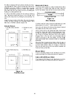
Figure 23
Ignition Control
(Viewed in an Upflow Installation)
Air Circulation Fan Timing
All items in this section refer to the air circulation fan, not
to the induced draft fan. The timing sequence for the
induced draft fan is not adjustable.
When a call for cooling occurs, the circulation fan will
come on following a five second delay. It will remain on
for 45 seconds after the call for cooling ends. This fan
timing is not adjustable.
During normal heating operation, the circulation fan will
come on 36 seconds after the gas valve opens. This
timing is not adjustable.
As shipped, the circulation fan will remain on for 90
seconds after the gas valve closes. If desired, this
timing may be adjusted. (Figures 23 and 24)
12
12
12
12
ON
OF
F
ON
OF
F
ON
OF
F
ON
OF
F
60
Second
Delay
90
Second
Delay
180
Second
Delay
120
Second
Delay
Switches viewed in an upflow installation.
Figure 24
X. Circulating Air and Filters
Ductwork - Air Flow
Duct systems and register sizes must be properly de-
signed for the C.F.M. and external static pressure rating
of the furnace. Ductwork should be designed in accor-
dance with the recommended methods of Air Condi-
tioning Contractors of America Manual D.
A duct system must be installed in accordance with
Standards of the National Board of Fire Underwriters for
the Installation of Air Conditioning, Warm Air Heating
and Ventilating Systems. Pamphlets No. 90A and 90B.
The filter is designed for high velocity heating and
cooling applications. Filters must be inspected, cleaned
or changed every two months or as required. It is the
owner's responsibility to keep air filters clean.
NOTE:
Dirty filters are the most common cause of inadequate
heating or cooling performance.
Guide dimples locate the bottom or side cutouts. Use a
straight edge to scribe lines connecting the dimples.
Cut out the opening on these lines. For bottom return air
connection, the bottom of the cabinet has to be re-
moved before the furnace is positioned on the raised
platform or set on top of the return air duct.
A closed return duct system must be used, with the
return duct sealed to the furnace casing. Supply and
return duct connections to the unit may be made with
flexible joints to minimize noise transmission. If a cen-
tral return is used, a connecting duct must be installed
between the unit and the utility room wall so the furnace
blower will not interfere with combustion air or draft.
The room, closet, or alcove must not be used as a
return air collecting chamber.
When the furnace is used in connection with a cooling
unit, the furnace should be installed in parallel with or
on the upstream side of the cooling unit to avoid con-
densation in the heating element. With a parallel flow
arrangement, the dampers or other means used to
control the flow of air must be adequate to prevent
chilled air from entering the furnace and, if manually
operated, must be equipped with means to prevent
operation of either unit unless the damper is in the full
heat or cool position.
When the furnace is installed without a cooling coil, it is
recommended that a removable access panel be pro-
vided in the outlet air duct. This opening shall be acces-
sible when the furnace is installed and shall be of such a
size that the heat exchanger can be viewed for visual
light inspection or such that a sampling probe can be
inserted into the air stream. The access panel must be
made to prevent air leaks when the furnace is in opera-
tion.
When the furnace is heating, the temperature of the
return air entering the furnace must be between 55°F
and 100°F.


