background image

26

Operating Instructions

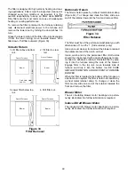
Refer to the following illustrations for the next twelve

steps.

Figure 27

Honeywell Model: VR-8205

Figure 28

White Rodgers Model: 36E36 or 36E37

O

F

F

ON

M

P

C

1

3

2

WR

INLET

OUTLET

Main Regulator

Adjust

Inlet Pressure Tap 

(Side of Valve)

Outlet Pressure Tap 

(Side of Valve)

Main

Solenoid

Redundant

Solenoid

ON/Off

Switch

Figure 29

White Rodgers Model 36E22 or 36E23

1. Close the manual gas valve external to the furnace.
2. Turn off the electrical power supply to the furnace.
3. Set room thermostat to lowest possible setting.

4. Remove the louvered door on the front of the fur-

nace by turning the latch screw 1/4 turn.

5. This furnace is equipped with an ignition device

which automatically lights the burner. Do not try to

light burner by hand.

6. 

White Rodgers Model 36E36 or 36E37 or Honeywell

Model VR-8205:

 Turn the gas control knob clock-

wise 

  to the OFF position for either the White

Rodgers gas valves or the Honeywell gas valve.

White Rodgers Model 36E22 or 36E23:

 Push the

selector switch to "OFF".

 7. Wait five minutes to clear out any gas. Then smell

for gas, including near the floor. This is important ,

because some types of gas are heavier than air.

8. If you smell gas following the five minute waiting

period in Step 7, immediately follow the instructions

on Page 2 of this manual. If you do not smell gas

after five minutes:

White Rodgers Model 36E36 or 36E37 or Honeywell

Model VR-8205:

 Turn the gas control knob counter-

clockwise 

   to the ON position for either the

White Rodgers 36E gas valve or the Honeywell VR-

8205 gas valve.

White Rodgers Model 36E22 or 36E23:

 Push the

selector switch to "ON".

9. Replace the louvered door on the front of the fur-

nace.

10. Open the manual gas valve external to the furnace.
11. Turn on the electrical power supply to the furnace.
12. Set thermostat to desired setting.

NOTE: 

There is an approximate 20 second delay be-

tween thermostat energizing and burner firing.

Check Gas Input Pressures

Gas supply pressure and manifold pressure with the

burners operating must be as specified on the rating

plate.

Checking Gas Pressure

Gas inlet pressure should be checked and adjusted in

accordance to the type of fuel being consumed.

Содержание GUC-X

Страница 1: ...plemental information Amana Refrigeration Inc Fayetteville TN 37334 ATTENTION INSTALLING PERSONNEL Amana Forced Air Central Furnace Design Complies With Requirements Embodied in The American National Standard National Standard of Canada Shown Below ANSI Z21 47 CAN CGA 2 3 Central Furnaces GUX X GUC X and GUD X Gas Fired Warm Air Furnace RECOGNIZE THIS SYMBOL AS A SAFETY PRECAUTION Installation Ins...

Страница 2: ... rating air temperature rise minimum or maximum CFM and motor speed connec tions K K K K Ke e e e e e e e e ept h i sl i t e r pt h i sl i t e r pt h i sl i t e r pt h i sl i t e r pt h i sl i t e ra a a a at u r t u r t u r t u r t u rei nas a f ei nas a f ei nas a f ei nas a f ei nas a fe p l a c e f e p l a c e f e p l a c e f e p l a c e f e p l a c e fo rf u o rf u o rf u o rf u o rf u t u r ...

Страница 3: ...stion and ventilating air openings in the front and top panels of the furnace must never be obstructed When the furnace is used in connection with a cooling unit the furnace must be upstream of or in parallel with the cooling unit For details see Sec tion VlI This furnace produces condensate as it operates Do not locate the furnace or its condensate drain age system in an area subjected to below f...

Страница 4: ...ion or maintenance on this product WARNING To prevent death personal injury or prop erty damage due to fire do not install this furnace in a mobile home trailer or recreational vehicle To ensure this upflow furnace operates safely and effi ciently it must be installed operated and maintained in accordance with these installation and operating in structions all local building codes and ordinances o...

Страница 5: ...ther spaces of the building Turn on clothes dryers and any appliance not connected to the common venting system Turn on any exhaust fans such as range hoods and bathroom exhausts so they will operate at maximum speed Do not operate a summer ex haust fan Close fireplace dampers d Follow the lighting instructions Place the appli ance being inspected in operation Adjust thermo stat so appliance will ...

Страница 6: ... material controlling dew point heating drying oxi dation or dilution safety exhaust odor control and air for compressors d In addition to air needed for combustion air shall be supplied for ventilation including all air required for comfort and proper working conditions for personnel e While all forms of building construction cannot be covered in detail air for combustion ventilation and dilution...

Страница 7: ...ee area of 1 square inch per 4 000 BTU per hour of total input rating of all equipment in the enclo sure See Figure 3 Figure 3 Equipment Located in Confined Spaces All Air from Outdoors Through Ventilated Attic See 5 3 3 b 3 When communicating with the outdoors through horizontal ducts each opening shall have a mini mum free area of 1 square inch per 2 000 BTU per hour of total input rating of all...

Страница 8: ...nada must be CSA listed Carefully follow the manufacturer s instructions in cutting clean ing and solvent cementing PVC or ABS pipes WARNING Solvent cements are combustible liquids and should be kept away from all igni tion sources i e sparks open flames and excessive heat Avoid breathing ce ment vapors or contact with skin and eyes 5 3 4 Specially Engineered Installations The requirements of 5 3 ...

Страница 9: ...2 2 3 4 2 2 2 2 2 3 3 Pipe Diameter for GUD070 GUD090 and GUD115 One Pipe Venting of Inside Elbows 5 to 10 feet 10 to 15 feet 15 to 20 feet 20 to 25 feet 25 to 30 feet 30 to 35 feet 35 to 40 feet 1 3 3 3 3 3 3 3 2 3 3 3 3 3 3 3 3 3 3 3 3 3 3 3 4 3 3 3 3 3 3 3 The inside feet of straight pipe and inside elbows repre sent the venting system from the furnace to the inside wall Follow termination inst...

Страница 10: ...ws should be used rather than 90 s The horizontal run must not have any sag that can hold condensate and should pitch up at least 1 4 inch per foot so that condensate will run back to the unit to drain Support the horizontal run at least every three feet Allow for some expansion and con traction from temperature fluctuations The normal di rection changes usually account for this but if you have a ...

Страница 11: ...rs insulation may be required on the outside of the vent pipe to prevent condensate from freezing Canadian installers must take note of the Additional Canadian Venting Requirements in this section Where required use 1 2 inch thick closed cell foam insulation such as Armaflex or Insultube NOTE Inspect the flue for leaks before installing any insulation If the combustion air pipe is to be installed ...

Страница 12: ...e terminals accord ingly to prevent exhaust vent and air intake blockages If installation above snow accumulation is required add additional elbows as shown in Figure 7 A 12 inch minimum clearance between the air intake and the highest anticipated snow level must be maintained The exhaust vent must penetrate the wall within the shaded region as shown in Figure 7 90 Medium Radius Elbow 12 Min Vent ...

Страница 13: ...ommon side wall maintain the clearances as shown in Figure 10 Always terminate all exhaust vent outlets at the same elevation and always terminate all air intakes at the same elevation 90 Medium Radius Elbows 12 Min Vents 24 Max 3 Min Air Intakes 24 Max 24 Max 3 Min 3 Min Figure 10 Horizontal Venting Of Multiple Units Sizing Of Exhaust Vent And Combustion Air Inlet Pipes Consult Tables 1 to 4 to s...

Страница 14: ...3 2 3 2 3 2 3 2 3 Inlet Outlet 3 2 3 2 3 2 3 2 3 2 3 2 3 3 4 Inlet Outlet 3 2 3 2 3 2 3 2 3 2 3 3 3 3 Table 2 90 000 BTUH Furnace No Of Vent Inside Feet Of Straight Pipe Each Run Elbows Type 5 10 10 15 15 20 20 25 25 30 30 35 35 40 1 Inlet Outlet 3 2 3 2 3 2 3 2 3 2 3 3 3 3 2 Inlet Outlet 3 2 3 2 3 2 3 2 3 3 3 3 3 3 3 Inlet Outlet 3 2 3 2 3 2 3 2 3 3 3 3 3 3 4 Inlet Outlet 3 2 3 2 3 2 3 3 3 3 3 3 ...

Страница 15: ...ent pipe and or combustion air pipe may be required Do not install insulation until after the flue system has been inspected for leaks as described below WARNING To prevent death personal injury or prop erty damage due to carbon monoxide carefully inspect the entire flue system both inside and outside the furnace after installation is completed to assure it is properly sealed and not leaking flue ...

Страница 16: ...ng a trunk line The gas pipe supplying the furnace must be properly sized based on gas flow required specific gravity of the gas and length of the run The gas line installation must comply with local codes or in the absence of local codes with the latest edition of the National Fuel Gas Code ANSI Z223 1 Natural Gas Capacity of Pipe In Cubic Feet of Gas Per Hour CFH Length of Nominal Black Pipe Siz...

Страница 17: ...In some cases the installer may also need to supply a transition piece from 1 2 inch to another pipe size The connectors or semirigid tubing must be pro tected against physical and thermal damage when installed Aluminum alloy tubing and connectors must be coated to protect against external corro sion when in contact with masonry plaster or insulation or are subject to repeated wettings by such liq...

Страница 18: ...Tanks and Piping Propane Gas Units WARNING To prevent death personal injury or prop erty damage due to fire or explosion caused by a propane gas leak install a gas detecting warning device Since rust can reduce the level of odorant in pro pane gas a gas detecting warning de vice is the only reliable way to detect a propane gas leak Contact a local pro pane gas supplier about installing a gas detec...

Страница 19: ...0 BTU hour Pipe or Nominal Pipe Size Tubing Tubing Size O D Type L Schedule 40 Length 3 8 1 2 5 8 3 4 7 8 1 1 8 1 2 3 4 1 1 1 4 1 1 2 Feet 10 39 92 199 329 501 935 275 567 1 071 2 205 3 307 20 26 62 131 216 346 630 189 393 732 1 496 2 299 30 21 50 107 181 277 500 152 315 590 1 212 1 858 40 19 41 90 145 233 427 129 267 504 1 039 1 559 50 18 37 79 131 198 376 114 237 448 913 1 417 60 16 35 72 121 18...

Страница 20: ... To avoid the risk of electrical shock wiring to the unit must be properly po larized and grounded WARNING To avoid electrical shock injury or death disconnect electrical power before changing any electrical wiring CAUTION Label all wires prior to disconnection when servicing controls Wiring errors can cause improper and dangerous op eration After servicing is completed al ways verify proper opera...

Страница 21: ... control module in this furnace is equipped with line voltage accessory terminals to be used for controlling the power to an optional field supplied humidifier and or electronic air cleaner CAUTION Label all wires prior to disconnection when servicing controls wiring errors can cause improper and dangerous op eration Verify proper operation after ser vicing Accessory Load Specifications Air Cleane...

Страница 22: ... or 180 Air Circulation Blower Gas Valve Ignitor Pressure Switch Induced Draft Blower Thermostat Integrated Control Diagnostic Light Signal Meanings Light Signal Refer To Abnormal Operation Integrated Control Section Continuous Light 1 Internal Control Failure 1 Flash 2 System Lockout 2 Flashes 3 Pressure Switch Stuck Closed 3 Flashes 4 Pressure Switch Stuck Open 4 Flashes 5 Open Limit Control 5 F...

Страница 23: ...r changed every two months or as required It is the owner s responsibility to keep air filters clean NOTE Dirty filters are the most common cause of inadequate heating or cooling performance Guide dimples locate the bottom or side cutouts Use a straight edge to scribe lines connecting the dimples Cut out the opening on these lines For bottom return air connection the bottom of the cabinet has to b...

Страница 24: ...on with one short flash followed by a longer off The control can be reset and brought out of lockout mode by turning the thermostat off and then back on The control will automatically reset after one hour 3 Pressure Switch Stuck Closed If the control senses the pressure switch is closed when the induced draft blower is off it waits until the fault is corrected The light code for this prob lem is t...

Страница 25: ...evice Figure 25 Roll Out Protection Device Except GUD Flame Roll Out Protection Device Figure 26 Roll Out Protection Device GUD CAUTION The cause must be investigated by a qualified servicer before any attempt is made to engage the roll out protection device and turn the furnace back on Electronic Control Module This furnace is equipped with a self diagnosing elec tronic control module In the even...

Страница 26: ...23 Push the selector switch to OFF 7 Wait five minutes to clear out any gas Then smell for gas including near the floor This is important because some types of gas are heavier than air 8 If you smell gas following the five minute waiting period in Step 7 immediately follow the instructions on Page 2 of this manual If you do not smell gas after five minutes White Rodgers Model 36E36 or 36E37 or Hon...

Страница 27: ... should be used for this measurement The manifold pressure must be measured with the burners operating To adjust the pressure regulator remove the adjustment screw cover on the gas valve Turn out counterclock wise to decrease pressure turn in clockwise to in crease pressure Only small variations in gas flow should be made by means of the pressure regulator adjust ment In no case should the final m...

Страница 28: ...e to the furnace as possible Thermometers must not be able to see the furnace s heat exchangers or false readings could be obtained 1 All registers must be open all duct dampers must be in their final fully or partially open position and the unit operated for 15 minutes before taking readings 2 The temperature rise must be within the range speci fied on the rating plate NOTE Air temperature rise i...

Страница 29: ...AUTION If you must handle the ignitor handle with care Touching the ignitor body with bare fingers rough handling or vibra tion could result in early ignitor failure Only a qualified servicer should ever handle the ignitor Have the furnace checked at least once every year before the heating season begins to be sure that there is adequate combustion air and that the vent system is working properly ...

Страница 30: ...34 To change and clean the filter slide one end of the retainer towards the front and remove filter Figure 34 Filter Retainer The filter must be of the permanent washable type with dimensions of 16 x 25 x 1 Side return s only Use a vacuum cleaner to clean out the blower area and the adjacent area of the return air duct Clean wash and dry the permanent filter Both sides should then be sprayed with ...

Страница 31: ...ing brush 7 The primary heat exchanger tubes can be cleaned using a round wire brush attached to a length of high grade stainless steel cable such as drain cleanout cable Attach a variable speed reversible drill to the other end of the spring cable Slowly rotate the cable with the drill and insert it into one of the primary heat exchanger tubes While reversing the drill work the cable in and out s...

Страница 32: ...c may be ordered by description 3 Parts are available from your Amana distributor Gas Valve LP Gas Orifice Natural Gas Orifice Blower Motor Flame Sensor Ignitor Gas Manifold Ignition Control Module Capacitor Pressure Switch Induced Draft Blower Collector Box Limit Switch Coil Front Cover Flame Roll out Switch Recuperator Coil Heat Exchanger Door Switch Transformer Blower Relay Blower Cutoff Board ...

Отзывы: