


Always
O
n UPS Systems
M0703_NX_Series_Operators_Manual
V1.25
2012-06-12 58
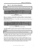
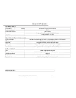
EXTERNAL INTERFACE
Alarm contacts
Standard
8 pre-defined contacts (consult user manual)
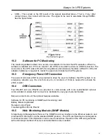
Serial communication
RS-232
Ethernet communications
SNMP standard
Emergency Power Off contacts provided (optional switch)
Input signals
Status displayed on LCD Panel
FRONT PANEL CONTROLS, SIGNALS & ALARMS
Active mimic Diagram
Represents the operational status of the UPS, with integrated LED's and power flow indicators.
LED display
Displays operational and fault conditions
Audile alarm
audible signal active when any alarm condition is present.
LCD Display
Display of UPS metering functions and event history (multi-language)
Push-Buttons
Inverter On, Inverter Off, Inverter Control, Up key, Down key, Enter key
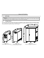
OPTIONAL FEATURES
IPRO
Isolated Parallel Redundant Operation
Remote status Panel
Active mimic diagram w/ Stop Operation and Summary Alarms.
Fire suppress protection
Drip shield
Dust protection
Air filters
Battery Cabinets
Additional matching battery cabinets to extend runtime
MECHANICAL DATA