background image


Always 

O

n UPS Systems 


M1306_GES-242NX-R Operators and Install Manual V1.0 2012-06-12 

17 

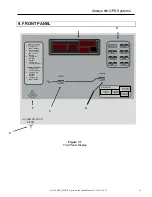
A: Metering-   

The GES-242N-R incorporates 4 digital displays for the user to monitor    


their Voltages and Currents.  


1. 

Input AC voltage:


Detects the input AC, allowing the user to monitor the 480 VAC  

   required 

to 

power 

the 

UPS. 


2. 

Battery Current:  

This ammeter detects both charge and discharge current of the  


batteries. The ammeter has a range of +/- 200 ADC. 


3. 

DC Output Voltage:

  Detects the DC output voltage supplied to the Load. 


4. 

DC Output Current:

  This ammeter detects the output current on the main bus bar. 


The ammeter has a range of +/- 200 ADC. 


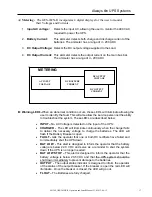
B: Warning LED’s-

When an abnormal condition occurs, these LED’s will illuminate allowing the 

user to identify the fault. This will also allow the service personnel the ability 
to troubleshoot the system. These LED’s are described below: 


INPUT – 

No AC Voltage is detected on the input of the UPS. 


CHARGER -

  The LED will illuminate continuously when the charger fails 

to deliver the necessary voltage to charge the batteries. The LED will 
flash if the Battery Breaker is open. 


FAULT -

 tells the operator that one or both DC rectifiers have failed and 

to immediately shut the UPS down 


BAT LOW  - 

This alert is designed to inform the operator that the battery 

voltage is below 22.0 VDC and serve as a reminder to shut the system 
down if the UPS is no longer needed. 


BAT LOW STOP – 

This alert is designed to inform the operator that the 

battery voltage is below 20.5 VDC and that the UPS system should be 
shut down immediately to prevent damage to the batteries.  


OUTPUT  - 

The output status indicator is designed to inform the operator 

of the status of the output breaker. If the breaker is open the red LED will 
illuminate.  Once the breaker is closed, the LED will go out. 


FLOAT –

 The Batteries are fully charged. 


AC INPUT  

VOLTAGE 


DC OUTPUT  

VOLTAGE 

DC BATTERY 

CURRENT 


DC OUTPUT 

CURRENT 


METERING 

Содержание GES-242NX-R

Страница 1: ...M1306_GES 242NX R Operators and Install Manual V1 0 2012 06 12 GES 242NX R 24VDC UPS Installation and Operators Manual...

Страница 2: ...Always On UPS Systems M1306_GES 242NX R Operators and Install Manual V1 0 2012 06 12...

Страница 3: ...3 1 Transport 5 3 2 Delivery 5 3 3 Storage 6 3 4 Site Environment Consideration 7 3 5 Unpacking 8 3 6 Cable Selection 9 4 80KVA DC UPS SYSTEMS LAYOUT DRAWINGS 10 5 DC UPS WIRING DIAGRAMS 11 6 TERMINAL...

Страница 4: ...s is a manual for Installation purposes only Do not attempt the start up of the DC UPS or apply power to the input terminals Factory authorized personnel shall inspect installation prior to start up a...

Страница 5: ...irectly Do not use outdoors The use of accessory equipment not recommended by Always On may cause an unsafe condition WARNING RISK OF ELECTRICAL SHOCK use extreme caution when removing covers All main...

Страница 6: ...r heat sources gas or electric heaters STORAGE Store the DC UPS in a dry location free of contaminants Storage temperature must be within 25 C 13 F to 55 C 131 F If the unit is stored for a period exc...

Страница 7: ...de before work is started This manual is designed as an aid tool in diagnosing problems that may arise Always On does not assume responsibility if information causes injuries Apart from the front door...

Страница 8: ...e lifted by crane use suitable lifting straps and spreader bars 3 2 Delivery Upon receiving the DC UPS system inspect the packaging integrity and the physical condition of the cabinets carefully In th...

Страница 9: ...ature range of 25 C 13 F to 55 C 131 F Exceeding this temperature range may cause damage STORAGE OF BATTERIES Although this system includes maintenance free batteries keep in mind that they are subjec...

Страница 10: ...proper heat dissipation and ventilated through the top openings optional ventilation booth is available upon request c Do not place any objects on the top of the DC UPS that might obscure the ventila...

Страница 11: ...destination carefully remove all the packaging material from the DC UPS and place the DC UPS in its final position This DC UPS system has passed all stages of production testing and final QC testing...

Страница 12: ...has to be sized according to the UPS power rating Sizing of circuit breakers fuses and cables for input utility output load and battery must meet the requirements of local and national electrical cod...

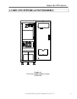
Страница 13: ...S 242NX R Operators and Install Manual V1 0 2012 06 12 10 Figure 4 1 Front View of System with Door Open Single Wide 4 24VDC UPS SYSTEMS LAYOUT DRAWINGS RECTIFIER DC OUTPUT WARNING LOW BAT BAT STOP IN...

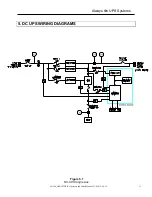
Страница 14: ...Always On UPS Systems M1306_GES 242NX R Operators and Install Manual V1 0 2012 06 12 11 Figure 5 1 DC UPS Single Line 5 DC UPS WIRING DIAGRAMS...

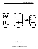
Страница 15: ...Always On UPS Systems M1306_GES 242NX R Operators and Install Manual V1 0 2012 06 12 12 Figure 5 2 DC UPS Power Cabling Diagram...

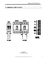
Страница 16: ...Always On UPS Systems M1306_GES 242NX R Operators and Install Manual V1 0 2012 06 12 13 6 TERMINAL STRIP LAYOUT Figure 6 1 Terminal Strip Layout...

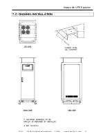
Страница 17: ...Always On UPS Systems M1306 GES 242NX R Operators and Install Manual 2 16 2009 Approved Eng Mgr T Naito 14 7 C CHANNEL INSTALLATION...

Страница 18: ...breaker b Wait 5 seconds for the Charger LED to start flashing c Turn ON the BATTERY breaker d Turn ON the OUTPUT breaker 1 2 Shutdown Procedure a Turn OFF the OUTPUT breaker b Turn OFF the BATTERY b...

Страница 19: ...E DC OUTPUT VOLTAGE DC BATTERY CURRENT DC OUTPUT CURRENT METERING ALARM SILENCE RESET E Startup Procedure 1 Turn ON the INPUT breaker 2 Wait 5 seconds for the Charger LED to start flashing 3 Turn ON t...
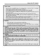
Страница 20: ...bed below INPUT No AC Voltage is detected on the input of the UPS CHARGER The LED will illuminate continuously when the charger fails to deliver the necessary voltage to charge the batteries The LED w...

Страница 21: ...is repaired and functioning properly the buzzer will re activate letting the user know to put the toggle switch back into the normal operating mode F Buzzer outlet There is a buzzer located behind the...

Страница 22: ...th DC rectifiers have failed and that the DC UPS should be immediately shut down LOW BATTERY This alert is designed to inform the operator that the battery voltage is below 22 0 VDC and serve as a rem...

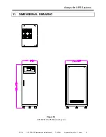
Страница 23: ...Always On UPS Systems M1306 GES 242NX R Operators and Install Manual 2 16 2009 Approved Eng Mgr T Naito 20 11 DIMENSIONAL DRAWING Figure 10 1 Figure 8 1 24VDC DC UPS Exterior Layout...

Страница 24: ...Fax 250 491 9775 Email qa alwayson com Website www alwayson com Software Questions Always On UPS Systems Inc 1 150 Campion Road Kelowna BC Canada V1X 7S8 Phone 250 491 9777 Ext 204 Fax 250 491 9775 Em...

Отзывы: