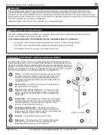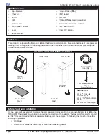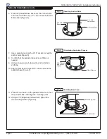
TAS12-AS1 &TAS12P-AS1 Installation Instructions
PUD3677R1-0
For Assistance: [email protected] +1 (909) 591-8431
Page 9
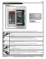
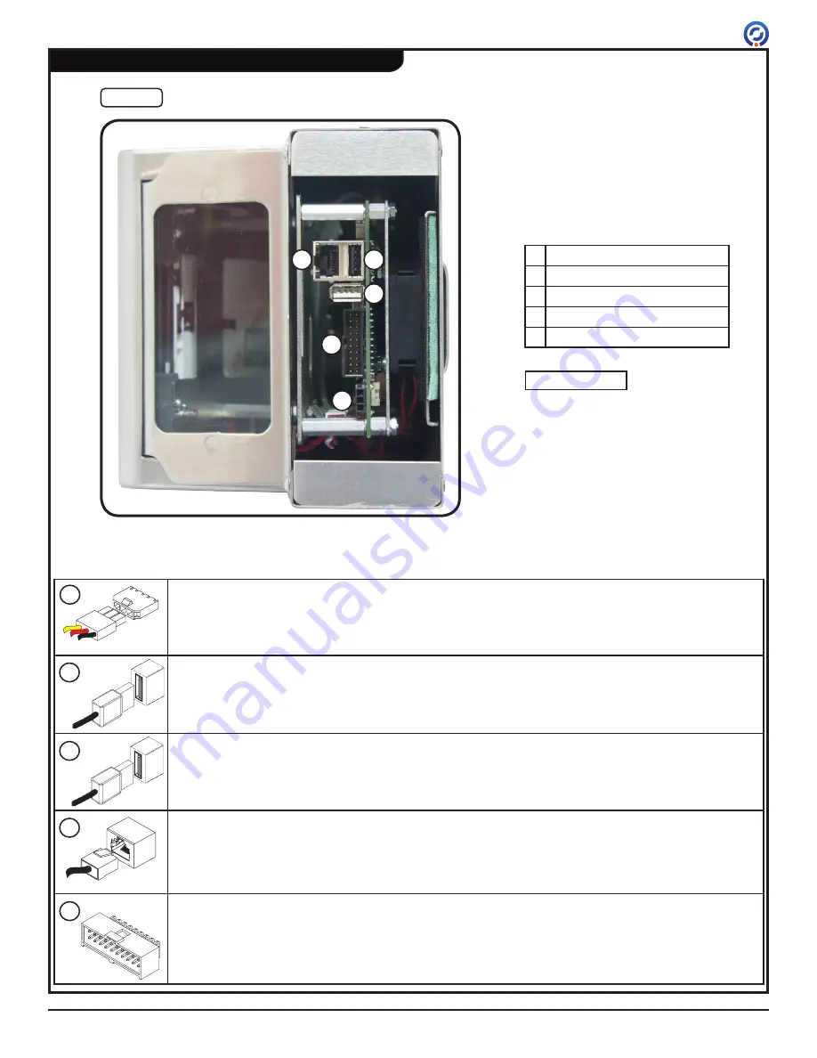
TAS12 Wiring
A
B
D
E
C
Fig. 11
TAS12 Inputs
Locate the following cables in the pedestal box. Use the instructions below to complete TAS12 wiring.
USB inputs are interchangeable.
NOTE
Power Cable
- Supplies power to the TAS12 unit. The power cable has 3 wires - red, black, and
yellow.
1. Locate the power supply's 3-pin power cable connector (A) and plug it into the TAS12 power
input (A).
Media Reader USB Cable (Optional for TAS12P-AS1 only)
- Allows an optional media reader
such as an RFID or magnetic stripe reader to communicate with the TAS12.
2. Locate the media reader's USB cable (B) and plug it into TAS12 USB input (B).
Thermal Printer USB Cable (TAS12P-AS1 only)
- Allows the TAS12 unit to communicate with the
thermal printer.
3. Locate the thermal printer's USB cable (C) and plug it into TAS12 USB input (C).
Shielded CAT6 Ethernet
Cable (Wired communication only)
- Used for communication with
local area network.
4. Locate the Ethernet cable (D) that was run up into the pedestal box and connect it to the
TAS12 Ethernet input (D).
Interface Input
- Allows the TAS12 to communicate with a peripheral device (i.e. turnstile or gate).
This input is only used when the TAS12 unit is controlling a peripheral device.
5. Locate the 20-pin connector (E) coming from the peripheral device and plug it into the interface
input located on the TAS12 (E).
A
B
C
D
E
A Power Input
B USB Input
C USB Input
D Ethernet Input
E Interface Input (See Below)


