background image

TAS12-AS1 &TAS12P-AS1 Installation Instructions

PUD3677R1-0 

       For Assistance: [email protected]  +1 (909) 591-8431  

Page 11

  Post-Installation Functions Check

The following is assumed:

•  The facility's communication network and GateLink10 server are online and operational.
• 

The TAS12-AS1's are configured with the appropriate network settings for the facility.

•  The Validation Service is running on the GateLink10 server.

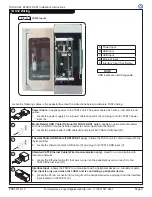
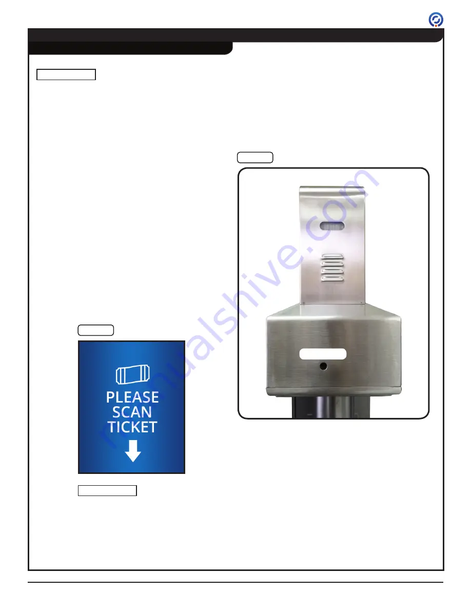
1.  Using a slim object, such as a pencil or pen, turn 

on the TAS12-AS1 by pressing the recessed ON/

OFF button on the rear side of the pedestal box 

[Figure 13].

2.  Upon powering on, the TAS12-AS1 will begin the 

boot up process. The entire boot up process will 

take approximately 40 seconds to complete. At 

the end of the boot up process, the TAS12 touch 

screen will display the "PLEASE SCAN TICKET" 

message [Figure 14]. 

NOTE

  Power On

Fig. 13

Power Button

Fig. 14

Please Scan Ticket 

Display Message

Power Button

(TAS12P-AS1 shown)

TAS12 display messages 

can be customized. The 

display message may differ 

from that shown above.

NOTE

Содержание TAS12-AS1

Страница 1: ...Manufacturing Company Inc 12660 Colony Street Chino CA 91710 Telephone 1 909 591 8431 Fax 1 909 628 1403 support alvaradomfg com www alvaradomfg com TAS12 AS1 TAS12P AS1 PUD3677R1 0 TAS12 AS1 TAS12P...

Страница 2: ...n for the installer and operator Please read these instructions For questions please contact Alvarado at 909 591 8431 Monday Friday 6 30am to 4 30 PST Please read this manual completely before install...

Страница 3: ...a 1D 2D barcode scanner color TFT display with touchscreen built in speaker and an advanced controller that communicates with Alvarado server applications via wired or wireless TCP IP The TAS12P AS1...

Страница 4: ...nsure that all conduit and corresponding lines are installed prior to installing the TAS12 AS1 The conduit stub up location should be dead center of the pedestal The maximum hole size for conduit is 2...

Страница 5: ...he anchor holes are not clear of debris the anchor bolts may not tighten correctly 5 Insert one anchor into each drilled hole Figure 3 The threaded end of the anchor must be inserted into the hole fir...

Страница 6: ...as needed 9 Using a torque wrench torque the anchor bolts to 20 ft lbs 10 Apply a thick bead of clear RTV silicone around the pedestal base Figure 5 11 Place the two halves of the pedestal base cover...

Страница 7: ...etely remove the screws 3 Gently close the pedestal box lid 4 Place the TAS12 onto the lid and slide the unit forward Figure 8 The base plate will act as a guide The dovetail plates will slide under t...

Страница 8: ...he terminal block inside the pedestal box Figure 10 2 Remove the protective cover from the terminal block 3 Attach ring connectors to the primary power LINE NEUTRAL and GROUND wires 4 Using a precisio...

Страница 9: ...the media reader s USB cable B and plug it into TAS12 USB input B Thermal Printer USB Cable TAS12P AS1 only Allows the TAS12 unit to communicate with the thermal printer 3 Locate the thermal printer...

Страница 10: ...ter roughly 885 of paper may be used Contact Zebra for information on custom paper roll stock If you have questions regarding paper compatibility contact Alvarado or Zebra Technical Support for assist...

Страница 11: ...r 1 Using a slim object such as a pencil or pen turn on the TAS12 AS1 by pressing the recessed ON OFF button on the rear side of the pedestal box Figure 13 2 Upon powering on the TAS12 AS1 will begin...

Страница 12: ...s menu 4 Perform the following Device Tests Figure 17 Set Green LED On Press this button to test the green attendant notification LED Press the button a second time to turn the LED off Set Yellow LED...

Страница 13: ...ripe reader with the magnetic stripe facing down Figure 19 The TAS12 will beep when the magnetic stripe has been read After reading the data is sent to the GateLink10 server for validation If the card...

Страница 14: ...he TAS12 AS1 for 10 seconds then power ON Figure 13 The display ribbon cable is not seated properly Check that the display ribbon cable is firmly seated in both connectors Figure 23 The TAS12 power ca...

Страница 15: ...ernet cable Figure 13 When network connectivity has been reestablished the TAS12 Ethernet port s green LINK light will illuminate The TAS12 s device IP is not recognized by the GateLink10 server or is...

Страница 16: ...ructions Page 16 For Assistance support alvaradomfg com 1 909 591 8431 PUD3677R1 0 Troubleshooting cont A Power Supply B Fuse 3A slo blo C Power Button D Primary Power Terminal Block A Fig 20 Pedestal...

Страница 17: ...ng cont A Touch Screen Board B Touch Screen Board Cable C Touch Screen Board Ribbon Cable C TAS12 Scanner Cable Fig 22 TAS12 Electronics Assembly Fig 21 TAS12 Touch Screen Board Fig 24 TAS12 Display R...

Страница 18: ...2 AS1 TAS12P AS1 Installation Instructions Page 18 For Assistance support alvaradomfg com 1 909 591 8431 PUD3677R1 0 TAS12 Backplane Board Fig 25 Correct DIP SW2 Configuration Fig 24A Troubleshooting...

Страница 19: ...PUD3677R1 0 For Assistance support alvaradomfg com 1 909 591 8431 Page 19 Appendix A Plan Elevation and Footprint Drawings TAS12 AS1 12 305 7 178 2 3 58 4 4 111 45 TYPICAL 5 6 142 8X 6 16 ANCHORING HO...

Страница 20: ...llation Instructions Page 20 For Assistance support alvaradomfg com 1 909 591 8431 PUD3677R1 0 Appendix A Plan Elevation and Footprint Drawings cont TAS12P AS1 16 1 409 2 3 58 4 4 111 45 TYPICAL 5 6 1...

Страница 21: ...AS1 TAS12P AS1 Installation Instructions PUD3677R1 0 For Assistance support alvaradomfg com 1 909 591 8431 Page 21 Revision History Revision Date Author Description 1 0 09 19 2014 A Flores Original do...

Страница 22: ...2014 Alvarado Manufacturing Company Inc This work may not be reproduced published or redistributed in whole or in part without the express prior written permission of Alvarado...

Отзывы: