background image

MULTITASKER™

400-0367-004

15

Example 2: 

Check for a signal on all outputs of the engine in 
slot 5 by sending the command [SDOC5]. In this 
case, there is a signal present on Output 1, but 
the rest have no signals. The system will return 
the following feedback:

[O01S1C05] [O02S0C05] [O03S0C05]
[O04S0C05] [O05S0C05] [O06S0C05]
[O07S0C05] [O08S0C05]

… [O63S0C05] [O64S0C05]

23. 

[MODE]

This command sets the matrix switch mode to 
Blocking or Non-Blocking. See the following 
examples for command functionality.

Command Format:  [MODEmCnUi]

m

= 1 = ON, 0 = OFF

Cn = Card ID (n = slot # from 1 to max slots)

Ui

= Unit ID (i = # from 0 to 9)

Example: NON-BLOCKING

Send the command [MODE0C5] to turn off
matrix switch blocking for the engine in slot 5. 
Next, send the command [I1O*C5] to connect 
input 1 to all outputs. In non-blocking mode, the 
inputs will be switched and the outputs will be 
enabled.

Example: BLOCKING ON

Send the command [I1O*C5] to connect input 1 
to all outputs. With  blocking  on, input 1 will be 
connected to all outputs, but only output 1 will 
be enabled. The remaining outputs will need to 
be enabled using the [ON] command.

Connecting a single output will result in the 
output being switched and enabled. For 
example, with blocking  on, sending the 
command [I22O22C5] will result in Input 22 
being connected to Output 22 and Output 22 will 
be enabled.

24.  

[HELP]

This command displays information available for 
the MultiTasker interface commands.

Command Format:  [HELPCnUi]

Cn = Card ID (n = slot # from 1 to max slots)

Ui

= Unit ID (i = # from 0 to 9)

Example:

In order to display the RS-232 commands 
available for the 

MT107-103

in  slot 5, send the 

command [HELPC5]. The commands along with 
a brief description will be displayed.

25.  

[…S] – Save

This command will save the configuration 
command being sent in memory.  Send the 
command [I1O8C5S] to the engine.  After reset 
or power up, Input 1 will be connected to 
Output 8 of the engine card slot 5.

26.  

[?]

This command will return general information 
about the MultiTasker and cards installed in the 
unit.

Command Format: [?Ui]

Ui

= Unit ID (i = from 0 to 9)

Example:

A MultiTasker with Unit ID  1 has a front panel 
with part number MT101-101 and contains an 
MT103-122, MT103-123 and 

MT107-103

. Send 

the command [?U1] and receive the following 
feedback:

[(MT101-101U1)(MT103-122C01)
(MT103-123C02)(MT107-103C10)]

MT101-101U1 = Panel Number and Unit ID

MT103-122C1 = An MT103-122 is in slot 1

MT103-123C2 = An MT103-123 is in slot 2

MT107-103C3 = An MT107-103 is in slot 10

Содержание MT107-103

Страница 1: ...MULTITASKER MANUAL PART NUMBER 400 0367 004 64X64 AUDIO MATRIX SWITCHER FOR MULTITASKER USER S GUIDE MT107 103 ...

Страница 2: ...S 3 PRODUCT DESCRIPTION 4 APPLICATION DIAGRAM 5 DIAGRAM 1 TYPICAL CONFIGURATION 5 DIAGRAM 2 INTERNAL VIEW 6 INSTALLING YOUR MT107 103 7 OPERATION 7 RS 232 CONTROL 7 DESCRIPTION OF COMMANDS 7 SUMMARY OF COMMANDS 22 MENU MODE 22 TROUBLESHOOTING GUIDE 26 LED IS NOT LIT 26 LED IS BLINKING RED 26 NO SOUND 27 ALTINEX POLICY 27 LIMITED WARRANTY RETURN POLICY 27 CONTACT INFORMATION 27 ...

Страница 3: ... solvents such as alcohol or thinner Do not use a wet cloth or water to clean the card Do not clean or touch any component or PCB 1 4 FCC CE NOTICE This device complies with Part 15 of the FCC Rules Operation is subject to the following two conditions 1 This device may not cause harmful interference and 2 this device must accept any interference received including interference that may cause undes...

Страница 4: ...er Each of the outputs is driven by a balanced audio line driver The output impedance is low and is capable of driving signals into 600 ohms including applications requiring long cable lengths The Matrix Engine may be easily configured to meet customer requirements by selecting the appropriate number of switching elements Selecting the proper configuration may be achieved using MTSetup The switchi...

Страница 5: ...MULTITASKER 400 0367 004 4 PRODUCT DESCRIPTION 4 ...

Страница 6: ...R 400 0367 004 5 APPLICATION DIAGRAM 5 DIAGRAM 1 TYPICAL CONFIGURATION MT107 103 STEREO CD PLAYER STEREO CD PLAYER STEREO CD PLAYER STEREO CD PLAYER AUDIO AMPLIFIER AUDIO AMPLIFIER AUDIO AMPLIFIER AUDIO AMPLIFIER ...

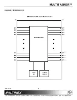
Страница 7: ...TITASKER 400 0367 004 6 DIAGRAM 2 INTERNAL VIEW MT107 103 64X64 Audio Matrix Engine IN64 IN63 IN61 IN62 IN4 IN3 IN2 IN1 IDC 64X64 MATRIX OUT63 OUT64 OUT61 OUT62 OUT4 OUT2 OUT3 OUT1 IDC POWER SUPPLY MAIN MP ...

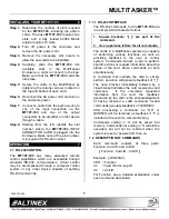
Страница 8: ...ccomplished through a computer control system or any other device capable of sending RS 232 commands 7 1 1 RS 232 INTERFACE The RS 232 commands for the MT107 103 are in a simple ASCII character format 1 Square brackets are part of the command 2 Use uppercase letters for all commands The cards in a MultiTasker system are capable of performing various functions as well as providing feedback to the u...

Страница 9: ...figuration settings Command Format CnUi Cn Card ID n slot from 1 to max slots Ui unit ID i from 0 to 9 Example There is an MT107 103 in slot 5 sending the command C5 will return feedback similar to the following Matrix mode non blocking Matrix number 1 Matrix size 64X64 Input offset 0 Output offset 0 Channel width 1 Channel space 0 Ch1 In1 Out1 ON AudioL32 Ch1 In1 Out2 ON AudioL32 Ch1 In64 Out64 O...

Страница 10: ... 2 digit from 00 99 yy Output Offset 2 digit from 00 99 kk Channel Width 2 digit from 01 32 ll Channel Spacing 2 digit from 00 31 Cn Engine Card Slot Number The slot number of the LEFT card of the engine is the Engine Card Slot number Ui Unit ID i from 0 to 9 S Save This property saves the configuration to Matrix ID memory and will allow the configuration to be recalled any time even after power u...

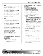
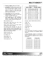
Страница 11: ...iguration is configured as a 64X64 Matrix with the following settings Number of Inputs 64 Number of Outputs 64 Input Offset 00 Output Offset 00 Channel Width 01 Channel Spacing 00 Default Configuration INPUT CARDS OUTPUT CARDS 8 3 2 1 1 2 3 8 Add On Add On Add On Base Unit Base Unit Add On Add On Add On 57 17 9 1 1 9 17 57 58 18 10 2 2 10 18 58 59 ç 19 11 3 3 11 19 è 59 60 20 12 4 4 12 20 60 61 21...

Страница 12: ...OWER UP In order to make configuration 1 of card 5 the default configuration when power is turned on send the M1C5S The feedback will be SAVEDC05 7 ONmmCn This command turns on a single output for the current matrix Command Format ONmmCnUi mm Output Number mm from 01 to 64 Cn Card ID n slot from 1 to max slots Ui Unit ID i from 0 to 9 Example There is an MT107 103 in slot 5 Turn ON output number 6...

Страница 13: ... connected to an input and enabled Command Format INmmSCnUi mm Input Number mm from 01 to 64 Cn Card ID n slot from 1 to max slots Ui Unit ID i from 0 to 9 Example 1 There is an MT107 103 in slot 5 Input 1 is connected to Output 1 Send the command IN01SC5 and receive the following feedback 1C05 Example 2 There is an MT107 103 in slot 5 Input 1 is connected to all outputs and all outputs are enable...

Страница 14: ...rent matrix and is used in conjunction with the and commands Command Format SELmmCnUi mm Input 2 digit from 01 to 64 Cn Card ID n slot from 1 to max slots Ui Unit ID i from 0 to 9 Example The Engine Card is in slot 5 Adjust the volume on Input 2 The current volume level is set to 10 After sending the following commands a better volume level of 15 is obtained 1 SEL02C5 The current volume level is 1...

Страница 15: ... no signal Cn Card ID n slot from 1 to max slots Example 1 Check for a signal on Input 1 of the engine in slot 5 by sending the command SDI01C5 If there is a signal present on Input 1 the system will return the following feedback I01S1C05 Example 2 Check for a signal on all inputs of the engine in slot 5 by sending the command SDIC5 In this case there is a signal on Input 1 but the rest have no si...

Страница 16: ... will result in the output being switched and enabled For example with blocking on sending the command I22O22C5 will result in Input 22 being connected to Output 22 and Output 22 will be enabled 24 HELP This command displays information available for the MultiTasker interface commands Command Format HELPCnUi Cn Card ID n slot from 1 to max slots Ui Unit ID i from 0 to 9 Example In order to display...

Страница 17: ...dicated the feedback type and the last three characters are the card s ID ex C05 See the STA1 command for further details FEEDBACK DESCRIPTION See Figure 1 for details on Matrix Configuration Connections and Input Volume Begin Feedback MT107 103C05 Model Number VR690 0159 006C05 Firmware Version ME1646400000100C05 Configuration MA010101 C05 Connections 01 16 MB010101 C05 Connections 17 32 MC010101...

Страница 18: ...ic feedback from the card and front panel The command affects any card with auto feedback capability not just the MT107 103 The default at power on or reset is STA0 OFF Command Format STA0 30 F FEEDBACK After processing a command an OK or ERR001 will be returned as feedback if F is included at the end of a command string 31 FBD This command turns the feedback delay on or off It is necessary when i...

Страница 19: ...o Input 1 Output 34 to Input 1 Input 3 Volume Input 51 Volume VD 32323232 32 C05 Input 52 Volume Input 64 Volume VA 32323232 32 C05 VB 32323232 32 C05 VC 32323232 32 C05 Input 33 Volume Input 34 Volume Input 35 Volume Input 36 Volume Input 48 Volume Input 49 Volume Input 50 Volume Input 4 Volume Input 17 Volume Input 18 Volume Input 16 Volume Input 20 Volume Input 32 Volume Input 19 Volume Input 2...

Страница 20: ...cards in the first unit may be numbered 1 10 and in the second unit 11 20 32 RSI This command resets the card ID s in the system After sending this command each card ID in the system will match the slot number of the card Use this command along with the SID commands that follow Command Format RSI Example Send the command RSI to the system with Unit ID 0 The card in slot 1 will have ID 1 the card i...

Страница 21: ...is command groups multiple cards in the enclosure allowing all the group members to be controlled simultaneously with the same command Each unit may define a maximum of eight groups In MultiTasker systems with audio and video cards boards are typically grouped as follows Group 1 Video Cards Group 2 Audio Cards Group 3 Video and Audio Cards If assigning group commands to button functions it is best...

Страница 22: ... Example The cards in slots 1 2 and 19 are part of group 5 Read the member data for group 5 by sending the command RDG5 The system will return feedback as follows G1 C1C2C19 The feedback shows G1 Group 1 and then the cards that make up Group 1 In this case Group 1 includes C1 C2 and C19 41 CLRG This command clears the members for a single group or for all groups The clear command restores the card...

Страница 23: ...18 Increment select property 19 Decrement select property 20 VOL Set absolute volume level 21 SDI Input signal detect 22 SDO Output signal detect 23 MODE Turn blocking on off 24 HELP Display help file 25 S Save command setting 26 Show system cards 27 C Show card information 28 STA1 Enable auto feedback 29 STA0 Disable auto feedback 30 F Show command feedback 31 FBD Feedback delay on off 32 RSI Res...

Страница 24: ... system needs to be connected to a computer running MTSetup or other RS 232 control software 2 Insert the card into an empty slot and push in all the way for a secure fit 3 Reset the system or power the system OFF and then ON 4 In MTSetup click the cursor in the Terminal Window and press the ENTER key 5 The system will interrogate the enclosure and return a list of cards installed and their slot l...

Страница 25: ...stem prompts requiring specific values are not shown See the examples following the menus for details MT107 103 MAIN MENU 1 MATRIX SETUP 2 SELECT MATRIX 1 3 OUT ON OFF 4 CONNECT IN OUT 5 SIGNAL DETECT 6 VERSION 7 STATUS 8 HELP 9 SAVE CURRENT SETTINGS ESC GO BACK KEY MT107 103 EXPANDED MENUS 1 MATRIX SETUP 1 SET MATRIX NUMBER 1 SET MATRIX NUMBER 1 9 ESC GO BACK KEY 2 SET NUMBER OF INPUTS 04 SET NUM...

Страница 26: ... list of available cards will be displayed 1 Define Matrix 1 Starting at the root menu or list of cards follow the keystrokes below to define and select Matrix 1 as a 64x64 matrix Enter List available cards 05 Select MT107 103 in slot 5 1 Select MATRIX SETUP 1 Select SET MATRIX NUMBER 1 Set matrix number to 1 2 Select SET NUMBER OF INPUTS 64 Set 64 inputs 3 Select SET NUMBER OF OUTPUTS 64 Set 64 o...

Страница 27: ...ard in all the way If the LED is still not on see Cause 3 Cause 3 Card cage slot has a problem Solution 1 Test the card in other slots of the card cage If the slot was damaged the card may work in other slots If other slots work and the LED lights the problem is the card cage slot The card cage may require service Call ALTINEX at 714 990 2300 If the other slots do not work and the LED is still not...

Страница 28: ...correct Solution Make sure that cables are properly connected Also make sure that the continuity and wiring are good If there is still no sound see Cause 4 Cause 4 The receiving device has a problem Solution Make sure the receiving device has power and is turned on If there is still no sound please call Altinex at 714 990 2300 ALTINEX POLICY 9 9 1 LIMITED WARRANTY RETURN POLICY Please see the Alti...

Отзывы: