background image

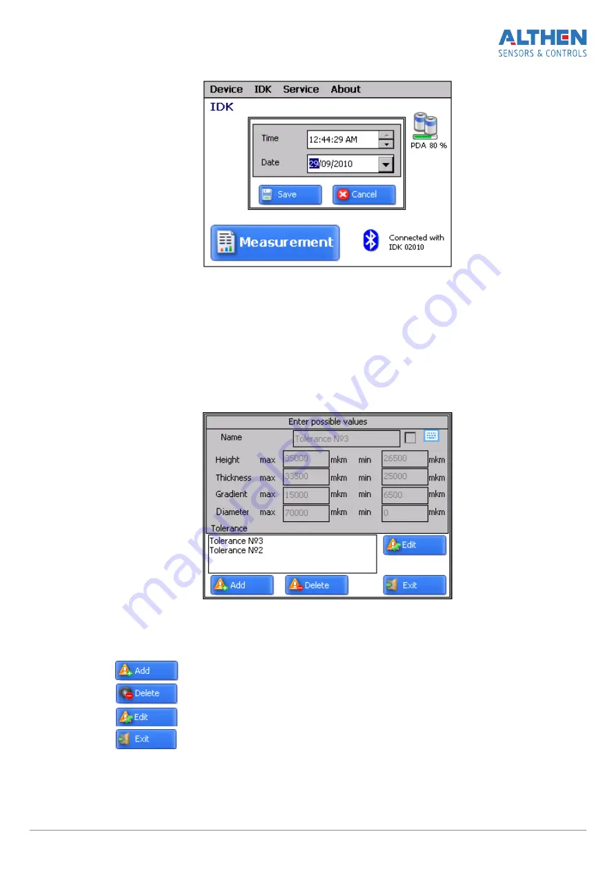
· write data and time
· press

Save

13.3.  Tolerances settings

The  program  automatically  controls  measured  geometric  parameters  for  going  out
beyond  the  tolerances  set.  It  is  possible  for  the  user  to  create  groups  of  tolerances.
Control  of  parameters  will  be  performed  for  a  selected  group.  To  set  tolerances  it
is  necessary  to:

· select

Service > Tolerances

 in the main window. View on the screen:

· adjust tolerances in the selected group or add a new group of tolerances and

write corresponding values. All values are in micrometers.

Buttons:

-

add new group of tolerances;

-

delete selected group of tolerances;

-

edit selected tolerance;

-

exit.

Page  1 9/29

Содержание FDK Series

Страница 1: ... ALTHEN Sensors Controls 26 avenue de la Méditerranée 34110 Frontignan France Tél 0033 0 4 67 78 61 66 sales althen fr USA Canada ALTHEN Inc Sensors Controls 2375 Woodacre Drive Oceanside CA 92056 USA Tel 1 858 633 3572 sales althensensors com Other Countries For our international sales partners please contact us by email at sales althensensors com www althensensors com Railway FDK BT Series Manua...

Страница 2: ...urn on 13 12 2 2 PDA turn on 13 12 3 On line measurement 14 12 4 Measurements with database maintenance 15 12 5 Browsing the database 17 12 6 Saving database on flash memory card 17 13 PDA program setting 18 13 1 Selection of measurement units 18 13 2 Data and Time settings 18 13 3 Tolerances settings 19 13 4 Database selection 20 13 5 Selection and formation of measurement scheme 20 13 5 1 Select...

Страница 3: ...ry and meets the requirements of the following standards EN 55022 2006 Information Technology Equipment Radio disturbance characteristics Limits and methods of measurement EN 61000 6 2 2005 Electromagnetic compatibility EMC Generic standards Immunity for industrial environments EN 61326 1 2006 Electrical Equipment for Measurement Control and Laboratory Use EMC Requirements General requirements 3 G...

Страница 4: ...urements saving in database Example FDK 70 250 850 1260 A BT Position of measurement 70 mm base of the gauge 250 mm bottom of measuring range 850 mm up of measuring range 1260 mm position of indication A BT Bluetooth presence Fig A Fig B 6 Complete set to be supplied Name Quantity Weight kg Wheel diameter measuring gauge FDK series 1 piece 0 5 Charger 1 piece 0 2 FDRF303 PDA option 1 piece 0 4 Cha...

Страница 5: ...e to the wheel edge and a measuring tip There are a digital numeric display and control buttons on the front panel of the gauge Charge connector for charging device connection and Bluetooth indication LED are situated on the top panel of the gauge Figure 1 Figure 1 1 7 2 Indication device option PDA is designed for control of the laser scanning module data reception from the scanning module indica...

Страница 6: ...s 1 Turn on button 2 Charging indication red blue LED 3 Connector to PC USB port or charging device 4 Flash memory card connector 5 Stylus 6 Bluetooth antenna Overall dimensions of PDA are shown in figure 3 Figure 3 Page 6 29 ...

Страница 7: ... the accumulator battery voltage became lower then the control level In this case the short term work is possible after pressing any key 9 2 Single measurement To perform measurement it is necessary to turn the power on press Red button The display shows place the gauge onto the wheel make sure the ball supports are tight against the roll surface and side sup ports are adjacent to the edge of the ...

Страница 8: ... total quantity of measurements averaged in this way can run up to 9999 Press Red button to reset averaging result at switching to another wheel For viewing the result of measurement with indication discreteness 0 01mm it is accessible only in a mode of direct indication it is necessary to press Blue button thus displayed result will be shifted to the left on one digit Next pressing Blue button wi...

Страница 9: ...or more than three seconds display will show bt On or bt OF press Blue button again Display will show Up by the pressing of Green button turn over the image the message Up will be turned over 1800 to save the changed parameters press Red button The display shows SAUE message press the Green button to confirm saving and Red to can cel saving of the changed parameters Image rotation function allows ...

Страница 10: ... display shows SAUE message press the Green button to confirm saving and Red to cancel saving of the changed parameters At brightness choosing one should take into account that increased brightness enhances power consumption and decreases the period till battery recharge moment 10 4 Millimeters Inches Tapes display set up To change the mode it is necessary to turn the power on press Red button pre...

Страница 11: ...reen button see p 11 3 For transition to next mode it is necessary to press Blue button Display shows CLbr b message the mode of device base calibration To get into this mode press Green button see p 11 4 To get out the mode of calibration press Red button 11 3 Calibration of the sensor zero When zero calibration mode being enabled the display shows the Johansson gauge value used for calibration i...

Страница 12: ...ging of values is made by pressing the Green button When editing is finished press the Red button and confirm or cancel saving of the parameter by pressing the Green button or Red button respectively Press the Green button and the reference diameter value starts blinking which means that the device must be placed onto a gage with the diameter value set at the previous step The device supports must...

Страница 13: ...ton to turn on the power The display shows ErrP message if the accumulator battery voltage became lower then the control level In this case the short term work is possible after pressing any key 12 2 2 PDA turn on Turn the PDA on by pressing the button 1 Fig 2 Activation indication 2 will show a green LED lit After the PDA is switched on some time will pass until automatic wireless communication i...

Страница 14: ...inst the roll surface and side sup ports are adjacent to the edge of the wheel press Green button Note hereinafter the button marked by green or red color is a corresponding button on the gauge or PDA screen In a 1 second the displays of the gauge and PDA will show the value of the wheel diameter When the diameter goes beyond set limits its value is highlighted with red col or Measurement button M...

Страница 15: ...een button pressings move the gauge to a new position and repeat the measuring The total quan tity of measurements averaged in this way can run up to 9999 Press Red button to reset averaging result at switching to another wheel 12 4 Measurements with database maintenance A fully functional work with the gauge involves maintenance of the measurements database To take measurements select in the main...

Страница 16: ...to be measured editing of the input wheel parameters a previous subsequent wheel a measured wheel a wheel to be measured next time a non measured wheel a measured wheel to be measured again measurement Measure the wheel offered by the program highlighted in green color as it is shown in par 12 3 After the measurement the PDA will show the value of diameter When a diameter falls out of the specific...

Страница 17: ... main window View on the screen for data filtering select data series and number of locomotive Buttons delete selected data 12 6 Saving database on flash memory card One of the ways to transfer database from PDA to PC is to use flash memory card To save database on the card proceed as follows connect cable FDRF505 42 to the PDA universal connector insert flash card to the respective cable connecto...

Страница 18: ...Selection of measurement units All parameters as well as measurement results can be presented in the metric system millimeters or in the English system of units inches To set measurement units it is necessary to select IDK Units of measuring mm inch select mm or inch option 13 2 Data and Time settings To set data and time select IDK Data Time in main window of the program View on the PDA screen Pa...

Страница 19: ...rances Control of parameters will be performed for a selected group To set tolerances it is necessary to select Service Tolerances in the main window View on the screen adjust tolerances in the selected group or add a new group of tolerances and write corresponding values All values are in micrometers Buttons add new group of tolerances delete selected group of tolerances edit selected tolerance e...

Страница 20: ...ss Select DB to delete the selected file press Delete to delete all files press Delete all to save file in TXT form press Export to exit from the window press Exit 13 5 Selection and formation of measurement scheme Measurement scheme is meant as a sequence of making measurements processing of wheels in the rolling stock The program automatically offers operator to perform measurement on a concrete...

Страница 21: ...w by using on screen keyboard type the scheme name select the number of axles select the number of coaches in the rolling stock train select the wheel processing scheme out of the options suggested press Save 13 5 3 Loading of a new measurement scheme If you can not form a new scheme in accordance with par 13 5 2 it is possible to use a special program for PC and then load the scheme to the PDA as...

Страница 22: ...ated in the directory used in the process of installation By default the following directory is used C Program Files RIFTEK Ikp5_db Language The directory contains two files RUS lng and ENG lng to support Russian and English languages respectively To create support file for any other language it is necessary to copy one of the existing files For example ENG lng under the other name for example GER...

Страница 23: ... to PC CD drive and start IDK exe file in the Software folder The main program window will appear 14 2 IDK PC connection turn the gauge ON install connection between the gauge and PC as described in par 18 select required port press Connect fro connection with the gauge If the connection is successful the Measurement button in the main program window becomes active You can begin to measure Page 2 ...

Страница 24: ...isplay shows the value of pressing counter n x where x quantity of averaged values in a 1 second display shows an average value over the set of metering over the quantity of Green button pressings move the gauge to a new position and repeat the measuring Press Red button to reset averaging result at switching to another wheel 15 Database maintenance software The ikp5_DB software is intended for ma...

Страница 25: ...nty policy Warranty assurance for the Wheel diameter gauge 24 months from the date of putting in operation warranty shelf life 12 months 18 Annex 1 Procedure of installation of Bluetooth connection between IDK and PC To install Bluetooth connection between the IDK and PC it is necessary to insert USB Bluetooth module to PC USB port continue installation of the equipment following instructions of t...

Страница 26: ...oth icon will appear in the screen activate IDK click right mouse key on the Bluetooth icon and select Add Bluetooth device Then Bluetooth installation wizard will start working tick the Device is installed and ready for connection select Next for search Page 2 6 29 ...

Страница 27: ... symbols and is set based on the IDK serial number For example if the IDK number is 02010 then Pin 0200 01309 Pin 0139 etc press Next and continue installation process when required drivers are installed the Bluetooth device will give a message with COM port outgoing which should be opened for connection with IDK during measuring In this case the port is COM3 Page 2 7 29 ...

Страница 28: ...directly on rolling stock without wheel set roll out Portable laser rail profilometer FPRP Series The main functions of FPRP are obtaining the information on the cross section profile of the working railhead surface full profile scanning and analyze of the railhead acting face visualization of the combined graphical images of actual and new cross section railhead profiles on the display of system ...

Страница 29: ...ting face visualization of the combined graphical images of actual and new disc brakes profiles on the display of system unit Automatic real time system for measurement of wheelsets geometrical parameters The system is designed for contactless automatic measure ment of geometrical parameters of railway wheels and uses a combination of 2D laser scanners mounted wayside in the track area The system ...

Отзывы: