background image

Operating manual F45 ElmoDrive

1.5/2016

GB

002

0000010040

Translation of the original operating instructions

Содержание ElmoDrive F45

Страница 1: ...Operating manual F45 ElmoDrive 1 5 2016 GB 002 0000010040 Translation of the original operating instructions ...

Страница 2: ... 25 3 5 1 Noise characteristic values 25 3 5 2 Dust 27 3 5 3 Electromagnetic compatibility 27 3 6 Ambient conditions 28 3 7 Safety information 29 3 7 1 Operational safety 29 3 7 2 Safety devices 32 3 7 3 Top safety hood riving knife 33 3 7 4 Handling batteries accumulators 34 4 Definitions 4 1 Description of machine 36 4 2 Terms 38 5 Transport siting and installation 5 1 Transport 40 5 2 Safety me...

Страница 3: ...ouble roller carriage 95 6 2 Working examples 97 6 3 Machine operation 105 6 3 1 Main switch 105 6 3 2 Switching the saw drives on and off 106 6 3 3 Setting the speed 108 6 3 4 Fitting the main saw blade 109 6 3 5 Saw blade recommendation 113 6 3 6 Table locking 114 6 4 Monitor controls ElmoDrive 115 6 4 1 Calibration 120 6 4 2 Height adjustment 122 6 4 3 Tilt adjustment 123 6 4 4 Motor driven rip...

Страница 4: ...utting line display 232 6 6 12 Coolant spray device 234 6 6 13 TIP SERVO DRIVE 235 7 Cleaning care 7 1 Safety measures 236 7 2 Maintenance cleaning by the user 237 7 3 Maintenance cleaning by qualified persons 249 7 3 1 Checking the winding shield 249 8 Faults problems troubleshooting 8 1 Machine diagnosis 250 8 2 Motor overload protection 251 8 3 Troubleshooting faults messages 252 8 4 Electronic...

Страница 5: ...ilable where the machine is being used They must be read and heeded by any person performing the fol lowing activities at or on the machine Operating including set up troubleshooting during operation elimination of production waste care disposal of operating and auxiliary materials Maintenance repair inspection Transport It is necessary to comply with national regulations on health and safety at w...

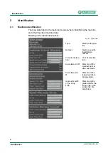
Страница 6: ...g of the stated descriptions Fig 2 1 Type plate Type Machine designa tion Number Machine specific identification number Year of construc tion Year of manufac ture Saw blade min Ø Diameter of the smallest permis sible saw blade Saw blade max Ø Diameter of the largest permissi ble saw blade Guide slot width of the riving knife Diameter of the guide bolts for the riving knife in the riving knife hol ...

Страница 7: ...3 Stuttgart Germany Identification number 0392 We hereby declare that the above mentioned product conforms with all applicable regulations of machi nery directive 2006 42 EC It fulfils the requirements of the following applicable directives Low voltage directive 2006 95 EC EMC directive 2004 108 EC The following harmonised standards have been applied DIN EN 1870 18 2007 2013 Safety of woodworking ...

Страница 8: ...Identification 8 Identification 0000010040 002 GB EC prototype testing certificate ...

Страница 9: ...Identification 9 0000010040 002 GB Identification ...

Страница 10: ...Identification 10 Identification 0000010040 002 GB GS test certificate ...

Страница 11: ...Identification 11 0000010040 002 GB Identification ...

Страница 12: ...Identification 12 Identification 0000010040 002 GB DGUV Test Certificate ...

Страница 13: ...Identification 13 0000010040 002 GB Identification ...

Страница 14: ...Identification 14 Identification 0000010040 002 GB C US Certificate ...

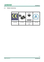
Страница 15: ...Identification 15 0000010040 002 GB Identification 2 3 Marks of conformity CE symbol GS symbol Wood dust appro ved mark C US mark ...

Страница 16: ...materials e g chipboard coreboard MDF board Solid wood Veneer with a suitable clamping device Gypsum plasterboard Cardboard Dimensionally stable plastics thermoset plastics thermoplastics Sawing these materials does not normally involve any risks in respect of dust chips and thermal degradation products Aluminium aluminium forging alloy in conjunction with the spraying unit option Danger warning H...

Страница 17: ... material Only circular blades which are solid chrome vanadium CV or tungsten carbide tipped TCT and have a maximum width of 20 mm are permitted for the main saw and milling grooving cutter The middle table strip and the cushioning disc must be removed when using a milling grooving cutter Saw blades with a maximum diameter of 120 mm are permissible for the scoring saw with a machine swivelling to ...

Страница 18: ...rs The pertinent accident prevention regulations as well as any other gene rally recognised technical safety and industrial medicine rules must be observed Repair work must be carried out by our own customer service or by an organisation that we have authorised Only original ALTENDORF spare parts may be used for this ALTENDORF will assume no warranty for any damage that is caused by using non orig...

Страница 19: ...rear cross end of the machine behind the main table length extension under no circumstan ces in the sliding table traverse area Fig 3 1 Machine operator positions Warning When removing workpieces at the rear of the machine ensure that you keep sufficient distance from the extending telescopic tube Non adherence may lead to knee injuries i Note Any other use is deemed as unintended ALTENDORF will n...

Страница 20: ...sing the handle Trimming without the trimming shoe Touching or manual infeed with automatically moving stops Saws without a riving knife Incorrect setting of the straight edge on the rip fence Use of coolant lubricants containing water Insufficient removal of wood and plastic residue prior to machining alumi nium Warning Always under all circumstances avoid the above mentioned types of work All ty...

Страница 21: ...tor driven sliding table Crushing between the motor driven tilt movement of the saw blade and the rip fence or workpieces lying in the tilting area Contact with live parts when the electrical installation area is open Damage to hearing as a result of working for long periods of time without hearing protection Emission of health endangering dust from operation without extraction Wear suitable glove...

Страница 22: ...able box mm kg kg kg kg kg kg mm mm 2250 855 1282 970 1495 114 175 131 142 203 230 2580x660x330 2060x960x500 3000 855 1282 970 1495 158 234 131 142 203 230 3330x660x330 2060x960x500 3200 855 1282 970 1495 170 250 131 142 203 230 3530x660x330 2060x960x500 3400 855 1282 970 1495 205 289 131 142 203 230 3730x660x330 2060x960x500 3800 855 1282 970 1495 212 304 131 142 203 230 4130x660x330 2060x960x500...

Страница 23: ... used Manufacturer Doepke switching devices these switching devices can also be purchased via Altendorf DFS4 040 4 0 30 B NK release current 300 mA DFS4 040 4 0 03 B NK for personal protection i Note Devices for differential protection to be provided by the customer In 230V400V systems devices are generally used that detect leakage currents 300 mA For switch off in the event of a fault RCDs residu...

Страница 24: ...7 20 5 5 200 220 50 19 8 23 2 35 7 5 200 220 50 26 5 29 9 35 5 5 380 420 50 60 11 5 13 5 20 7 5 380 420 50 15 5 17 5 25 11 380 420 50 22 5 24 5 35 VARIO tilting to one side 380 420 50 60 36 0 38 0 35 VARIO 5kW tilting to both sides 380 420 50 60 36 0 38 0 35 VARIO 6 5kW tilting to both sides 380 420 50 60 36 0 38 30 35 5 5 200 220 60 20 0 23 5 35 7 5 200 220 60 24 0 28 0 35 5 5 600 60 7 5 8 5 20 7...

Страница 25: ...s it cannot be reliably deduced from this whether or not additional precau tionary measures are needed to protect operators Sound power level dB A Emission sound level at the workplace dB A Tools Idling_____LWA 87 3 Cutting__LWA 96 6 Idling_____LPA 77 4 Cutting__LPA 84 0 Circular saw blade 300x3 2 96 WZ n 3987 rpm Idling_____LWA 101 3 Cutting__LWA 104 2 Idling_____LPA 95 7 Cutting__LPA 92 1 Circul...

Страница 26: ...40 002 GB Factors that influence the immission level at the workplace include the duration of exposure room characteristics other sources of noise such as the type and number of neighbouring machines and other working processes involving noi se emission ...

Страница 27: ...force in Germany The machines are tested concerning wood dust in accordance with the BGI 739 1 The machines bear the DGUV mark with the additional wood dust mark holzstaubgeprüft Consequently a company operating the machine in Ger many is exempt from the obligation to perform measurements at the workplace in accordance with TRGS 553 3 5 3 Electromagnetic compatibility EMC Electromagnetic Compatibi...

Страница 28: ...nd storage The machine must not be used in an environment with explosive or corrosive gases The ambient temperatures for transport and storage range from 25 C to 55 C and 70 C is permissible for a short time The maximum air humidity must not exceed 90 and condensation must be avoided in all cases ...

Страница 29: ...s of the European standard EN 847 1 2005 A1 2007 When grooving with milling tools only use milling tools for manual feeding with a groove width less than or equal to 20 mm 5 mm for machines with the option Saw blade tilting to both sides marked with MAN according to the European standard EN 847 1 2005 A1 2007 Only fit saw blades with the dimensions described in the technical data The diameter of t...

Страница 30: ... saw blade diameters from 250 mm to 550 mm With respect to their thickness they match the cutting line widths of commercially available tungsten carbide tipped saw blades If other saw blades e g made of chrome vanadium CV are used select a riving knife thickness that lies between the cutting line width and the main blade thickness Such riving knifes can be obtained from the trade or directly from ...

Страница 31: ...prevent ignition of remaining chips dust The sawdust generated during cutting not only impairs visibility but is also partially hazardous to health Therefore the machine must be connected to a chip extraction system with both extraction sockets The minimum air speed at the lower extraction socket must be at least 20 m s When the machine is switched on the extraction system must switch on at the sa...

Страница 32: ...m jamming between the fence and the rising gear rim or can be switched over to a low guide sur face for cutting narrow and flat workpieces allowing adequate space for the guide hand together with the possibility of lowering the top safety hood onto the workpiece here too Trimming hold down to clamp and hold down untrimmed solid wood to secure against slippage in the course of trimming Electrical i...

Страница 33: ... requi red for sawing above the machine table with a safeguard against lifting beyond the maximum cutting height of 5 mm Rollers integrated in the safety hoods at the leading and trailing ends facilitate both feeding workpi eces and pulling back workpieces if workpieces have a slightly different thickness Laterally displaceable protective hood for machines with the option Saw blade tilting to both...

Страница 34: ...he risk potential of lithium batteries is in addition to the product design prima rily determined by the module or system capacity The types used by Altendorf are low capacity lithium batteries batteries 1 kg The information for dama ge prevention applies to both new and used batteries General safety regulations Always observe the following safety regulations Adhere to all specifications by manufa...

Страница 35: ...Product description 35 0000010040 002 GB Product description Source VdS 3103 2012 06 01 Lithium batteries Excerpt of the GDV leaflet for damage prevention ...

Страница 36: ...Definitions 36 Definitions 0000010040 002 GB 4 Definitions 4 1 Description of machine Fig 4 1 Description of the sliding table saw ...

Страница 37: ...le 5 Rip fence 6 Trimming hold down device clamping shoe 7 Table insert 8 Machine table 9 Table length extension 10 Fixing elements 11 Protective hood holding fixture 12 Push stick 13 Sliding table 14 Crosscut fence 15 Sliding table handle 16 Movable operating terminal 17 Additional fixing elements on the rear end of the sliding table optional ...

Страница 38: ... fastened to the machine such that it can be tilted out of the work position without tools or similar equipment Safety appliance Additional device that is not an integral part of the machine but helps the opera tor to feed the workpiece safely e g a push block or push stick Kick back Unexpected sudden movement of the workpiece or parts of it opposite to the di rection of feed in the course of sawi...

Страница 39: ...Definitions 39 0000010040 002 GB Definitions ...

Страница 40: ...gree of dismantling of the sliding table saw depends on the transport conditions and the options supplied with the machine The sliding table is al ways shipped dismantled into several installation assemblies Sensitivity Particular care must be taken when transporting the sliding table saw in order to avoid damage from force or poor loading and unloading Knocks and conden sation due to extreme temp...

Страница 41: ...e a load bearing strength suitable for the machine weight and should be flat and level Select an installation site that provides enough clearance around the sliding ta ble saw allowing for the space requirements shown in the figure and the size of the workpieces to be cut In addition observe the safety clearances to parts of the building and other machines in order to eliminate the risk of crushin...

Страница 42: ...nsport siting and installation 0000010040 002 GB Danger Danger of crushing For operation with the max workpiece weight secure the machine against tilting Ensure that there is sufficient safety clearance from building parts and other machines ...

Страница 43: ...width 280 mm Motor driven adjustment PA Cutting width 360 mm Dimension B Sliding table length 360 mm Dimension C Sliding table length 290 mm sliding table length 30 mm with TSD Dimension D Crosscut fence 1890 max 3420 mm Crosscut mitre fence and PQS 1960 max 3690 mm CNC crosscut fence UNO DUO 2200 max 3670 mm Fig 5 2 Space requirement ...

Страница 44: ...llation 0000010040 002 GB Fixing A fixing element is provided on the side of the machine frame to ensure the ma chine stays in position Once the sliding table saw has been set up loosen the screws and lower the fixing down to the floor Then retighten the two screws ...

Страница 45: ...3 Installation 5 3 1 Telescopic tube for swinging arm Assembly telescopic tube Standard Compact Fig 5 3 Installing the telescopic tube 1 Undo the cheese head screw 2 Push in the telescopic tube from the front through the housing for the swinging arm 3 Insert and tighten the cheese head screw ...

Страница 46: ...e 4th axis Fig 5 4 Swivelling arm 4th axis 1 Support bolt 2 Plug type connection plate telescopic tube 3 Plug type connection plate swivelling arm housing i Note The two plug type connections have a different number of pins The number of pins is 3 and 5 The 5 pole connection is marked red Fig 5 5 Plug type connections ...

Страница 47: ...holes on the table top face end Loosely secure to the table top with two M10 nuts and U shaped washers Screw fit the TPL to the aluminium brackets 6 Tighten the M10 nuts If necessary correct the alignment and flushness by readjusting the sup port screws 4 Fig 5 6 Installing the main table length extension 1 TPL board 2 Support arm 3 Fastening screw M10 4 Support screw 5 Stationary installed adjust...

Страница 48: ...rt the fastening screws of the support arms into the holes on the table top face end Loosely secure to the table top with two M10 nuts and U shaped washers Screw fit the TPL to the aluminium brackets Tighten the M10 nuts If necessary correct the alignment and flushness by readjusting the adjus table feet 3 and or the support screws 1 Fig 5 7 TPL 1600 2000 1 Support screws 2 Fastening screws 3 Adju...

Страница 49: ... bar 1 Fit the measuring bar easily with M6x30 countersunk screws 1 2 Knock a 6x45 clamping pin 2 through 3 Tighten the countersunk screws 1 Fig 5 9 Installing the main table width extension 1 TPV board 2 Support arm 3 Fastening screw M10 4 Support screw 5 Stationary installed adjusted bracket on the cast table top 6 Fastening screws for TPV on bracket ...

Страница 50: ...the TPV onto the brackets on the table top and insert the fastening screws of the support arms into the holes on the table top face end Loosely secure to the table top with two M10 nuts and U shaped washers Screw fit the TPV to the aluminium brackets 6 Tighten the M10 nuts If necessary correct the alignment and flushness by readjusting the sup port screws 4 ...

Страница 51: ...lace the supporting pipe of the cross slide 1 onto the bolt 8 of the telesco pic tube Tilt the cross slide to the sliding table suspend and clamp using the eccentric lever 2 for the operation of the eccentric lever refer to the following pages Fig 5 10 Installing the cross slide 1 Support pipe 2 Eccentric clamping lever 3 Workpiece support 4 Crosscut fence 5 Crosscut fence clamping 6 Extendable cr...

Страница 52: ...falling down To remove the cross slide pull out the safety locking mechanism and push up the clamping lever The safety mechanism engages in the hole 4 The cross slide can now be removed completely When assembling the cross slide first hook it in pull out the safety locking me chanism push the clamping lever all the way to the fixed stop Release the sa fety locking mechanism Fig 5 11 Clamping lever...

Страница 53: ...ide without a risk of the cross slide falling down To remove the cross slide pull out the safety locking mechanisms and turn them The safety locking mechanisms engage The cross slide can now be re moved completely When assembling the cross slide first hook it in and push the clamping lever all the way to the fixed stop Undo the safety locking mechanism and turn to enga ge Fig 5 12 Cross slide clam...

Страница 54: ...apered surfaces Changing the 90 crosscut fence 1 Undo the clamping bolts 1 2 Move the crosscut fence to a new position ensure that the clamping bolts are inserted into the grooves 3 Tighten the clamping bolts 1 positioning is carried out by means of the tapered surfaces Fig 5 13 Installing the 90 crosscut fence Warning In the case of the tilting to both sides option only use the crosscut fen ces s...

Страница 55: ... the handle of the degree scale clamping Carefully turn the crosscut mitre fence by 90 so that the ball bearing can be inserted in the groove of the sliding table and the threaded bolt of the clamping degree scale in the groove of the profile Fasten the handle of the clamping degree scale Fig 5 14 Crosscut mitre fence operating elements 1 Clamping lever 90 position 2 Clamping degree scale 3 Clampi...

Страница 56: ...Transport siting and installation 56 Transport siting and installation 0000010040 002 GB Fig 5 15 Installing the WGA 1 Clamping degree scale 2 Clamping pivot point 3 Ball bearing ...

Страница 57: ...allation 90 clamping Fig 5 16 90 clamping 1 Support roller 2 Clamping lever 3 90 stop 4 Pressure piece on the clamping lever 5 Guide bolt s Fig 5 17 Crosscut mitre fence left hand side 1 Clamping screw telescopic extension 2 Guide groove for 90 position 3 Clamping piece 90 position ...

Страница 58: ...gree scale and push the guide carriage into the middle Position the T nut for pivot clamping so that there is enough clearance to the pivot Push the ball bearing over the groove in the sliding table Carefully turn the crosscut mitre fence 90 and raise it so that the bolt enters the degree scale groove and the ball bearing enters the sliding table groove Fig 5 18 WGA_LD 1 Clamping lever 90 position...

Страница 59: ... the T nut with clamping screw 3 into the pivot Swivel the WGA to its 90 position and clamp with clamping lever 1 Tighten the clamping screws Operating elements Fig 5 19 WGA_LD 1 Telescopic extension 2 Clamping telescopic extension 3 90 stop 4 Guide groove 90 position 5 Clamping degree scale 6 Clamping pivot point 7 Guide roller sliding table 8 Clamping lever 90 position 9 Indexing bolt angle meas...

Страница 60: ...allation 0000010040 002 GB Fig 5 20 90 clamping 1 Support roller 2 Clamping lever 3 90 stop 4 Pressure piece on the clamping lever 5 Guide bolt s Fig 5 21 WGA_LD LH side 1 Clamping screw telescopic extension 2 Guide groove 90 position 3 Clamping piece 90 position ...

Страница 61: ...n CNC crosscut fence Operating elements CNC crosscut fence UNO 90 Fig 5 22 CNC crosscut fence UNO 90 1 Stop fence 2 Axis drive 3 Axis extension 4 Electrical connection 5 Clamping screws 6 Indexing bolt extension 7 Clamping screw extension 8 Clamping lever cross slide 9 Clamping C profile ...

Страница 62: ...ension installation Insert the extension into the guide until the indexing bolt engages Tighten the clamping screw When using the second throw over stop the adjustable dimension increa ses by 1000 mm Fig 5 23 Extension CNC crosscut fence UNO 90 1 1000 mm extension piece 2 Indexing bolt 3 Clamping screw ...

Страница 63: ...Transport siting and installation 63 0000010040 002 GB Transport siting and installation Fig 5 24 Extension installation 1 Locking hole extension 2 Indexing bolt 3 Clamping extension ...

Страница 64: ...rt siting and installation 0000010040 002 GB Operating elements 4th axis DUO 90 Fig 5 25 Operating elements 4th axis DUO 90 1 4th axis DUO 90 2 90 stop 3 Safety frame 4 Clamping 5 Drive unit 6 Cross slide clamping 7 Cross slide locking mechanism ...

Страница 65: ...e of the cross slide on the bolt of the telescopic tube Swing the cross slide to the sliding table hook it in and clamp it with the clamping mechanism Engage cross slide locking mechanism Fig 5 26 Operating elements 1 4th axis DUO 90 2 Drive unit 3 90 stop 4 90 clamping screw 5 Handle for guide plate 6 Clamping 7 Extension 8 Throw over stop 2 9 Throw over stop 1 10 Cross slide clamping 11 90 mount...

Страница 66: ... Push the guide plate into the mounting Swivel and tighten 90 clamping screw into the 90 stop Tighten the guide plate clamp Insert the plug connectors of the 4th axis underneath the telescopic tube Fig 5 27 Installing the 4th axis 1 4th axis DUO 90 2 Safety frame 3 Cross slide i Note If the safety frame is not installed adjustment movements are only pos sible in HOLD TO RUN mode ...

Страница 67: ...Fig 5 28 Electrical connection 1 Socket 1 2 Socket 2 Warning The plug connectors have 3 and 5 poles are marked in different colours and must only be connected or disconnected when the main switch is switched off Non adherence can lead to destruction of the plug connectors or the electronics ...

Страница 68: ...lows Place the supporting pipe of the cross slide on the bolt of the telescopic tube Swing the cross slide to the sliding table hook it in and clamp it with the clamping mechanism Engage cross slide locking mechanism Fig 5 29 Operating elements 4th axis DUO Flex 1 4th axis DUO Flex 2 90 stop 3 Angle measuring unit 4 Clamping pivot point 5 Clamping cross slide 6 Cross slide locking mechanism 7 Driv...

Страница 69: ...gree scale Position the guide carriage such that the distance between the stop fence and the hole in the guide carriage is 100 mm Turn the clamps 90 in the longitudinal direction Turn the 4th axis by 90 Check the guide roller in the roller carriage groove Push the pivot clamp to the right into the clamping plate and tighten the bolts Fasten the handle of the Degree scale clamping Insert the plug c...

Страница 70: ...1 Electrical connection 1 Socket 1 2 Socket 2 3 90 clamping Warning The plug connectors have 3 and 5 poles are marked in different colours and must only be connected or disconnected when the main switch is switched off Non adherence can lead to destruction of the plug connectors or the electronics ...

Страница 71: ...ng the outer fixing screws 3 Only tighten the middle fixing screw loosely Fig 5 33 Installing the middle carriage 1 Place the middle carriage on the bottom carriage so that the interlock is pointing to the right 2 Push the middle carriage to the right until the 1st double roller is still just resting on the round bars If this is not observed in the case of the TIP SERVO DRIVE the end position sens...

Страница 72: ...ws in the clamping piece Fig 5 34 Installing the top carriage 1 Carefully push on the top carriage making sure it is not skewed watch the e chain 2 Carefully push the guide rails onto the double rollers 3 Push the top carriage towards the left all the way to the stop Fig 5 35 Back stop 1 Back stop 2 Clamping piece for rear stop ...

Страница 73: ...0 002 GB Transport siting and installation Fig 5 36 Central fixing 1 Tighten the central fixing screw 2 Check that the sub rollers are correctly adjusted Fig 5 37 Bracket on the bottom carriage 1 Fix the bracket to the bottom carriage with 3 screws ...

Страница 74: ...ng and installation 0000010040 002 GB Fig 5 38 Bracket on the bottom carriage Fig 5 39 Position of e chain 1 Place the bottom e chain on the bracket on the bottom carriage 2 Run the cable into the machine frame through the opening in the bottom carriage ...

Страница 75: ...crew the first link of the e chain onto the bracket using 2 screws Fig 5 41 Switch cabinet 1 Connect the plug to the switch cabinet 2 Tighten the cap nut Warning The connectors have 3 and 5 poles Ensure you plug the 3 pole connector into the 3 pole socket otherwise the connector will be destroyed Observe the colour marking ...

Страница 76: ...Transport siting and installation 76 Transport siting and installation 0000010040 002 GB Fig 5 42 Fastening the e chain cable 1 Remove all the packing tape 2 Screw on the cover profile ...

Страница 77: ...ge All work on the electrical equipment including connection to the mains supply may only be performed by a qualified electrician Disconnect the machine from the mains supply before working on the electrical equip ment After connecting the supply line check the rotationaldirection of the main saw motor by briefly starting up and if necessary correct it by interchanging the two outer conductors in ...

Страница 78: ...Transport siting and installation 78 Transport siting and installation 0000010040 002 GB Fig 5 44 Circuit diagram ...

Страница 79: ...aw motor S 1 Sliding table safety switch S 2 EMERGENCY STOP button S 3 Temperature monitor for scoring saw motor S 1 Machine door cover plate safety switch E 1 Multifunction module F 1 F 2 Control fuses primary F 4 F 6 Scorer motor option F 7 F 9 Control fuses secondary F 10 F11 SPRAY LASER control fuse option F 12 F 14 CEKON option K 1 M K 5 M Motor contactors K 5 E Supply voltage contactor for a...

Страница 80: ...od are under 2 mg m3 When the machine is attached to a correctly functioning extraction system with an air speed of at least 20 m s measured at the connection socket you can assume it is and will stay compliant with the technical reference concentration TRK value for wood dust that is in force in Germany For perfect and safe operation the machine must be connected to the extraction system at the e...

Страница 81: ... device SPRAY make sure that you use a suita ble moisture extraction system in order to avoid faults Check the function of the extraction system at regular intervals A spark extinguishing system should be installed as a precaution to prevent fires and explosions in filter systems silos and other produc tion environments Ensure that the extraction system is suitable for extracting aluminium chips A...

Страница 82: ...he sub rollers The sub rollers must run smoothly against the start slope at the start and end of the raceway They should be set so that they can be held by hand with noticea ble force and that they slip while the sliding table is moved Setting of the sub rollers The sub rollers have eccentric bearings and can be adjusted The sub rollers are set so that they can be held by hand with noticeable forc...

Страница 83: ...ace a rip fence straight edge on the sliding table and move the table into the middle position Move the sliding table forward and backward the main table must be approx 1 10 mm lower Adjusting the main table Release the lock nuts 1 of the 4 stay bolts adjust the main table and tighten the lock nuts Fig 5 47 Adjusting the main table ...

Страница 84: ...ions A and B with a tolerance of 0 5 mm if necessary correct the setting with EX 1 and EX 2 The dimension between the bottom edge of the crosscut fence profile and the top edge of the top carriage profile see fig 2 is a feature for the tolerance of the swivel arm setting The dimension must not exceed the cut length possible with the cross slide between 0 1 and 0 9 mm check with feeler gauge Fig 5 ...

Страница 85: ...table it must be possible to move the cardboard freely in every position The crosscut fence must be parallel to the surface of the sliding table Setting Adjust the height of the swinging arm bolt and fix it with a lock nut Check that the swinging arm is parallel if the gap changes in accordance with the position of the sliding table Fig 5 50 Checking the cross slide height Fig 5 51 Adjusting the c...

Страница 86: ...he rising teeth pass only a slight fluttering should be heard compared to the noise of the cutting teeth Setting Release the sliding table mounting components at both ends and in the centre if installed Release the lock nuts of the stop screws Adjust them as required and fix them with lock nuts again Then push the sliding table against the stop screws and re tighten all fastening screws Rip fence ...

Страница 87: ... extension The degree of free cut on the rip fence can be altered by adjusting the middle lock nuts Tighten the nuts on the bolts connecting the round bar and the table width extension Setting Electromotive rip fence Release clamping screws 1 Set the free cut by adjusting setscrews 2 Tighten clamping screws 1 Fig 5 52 Setting free cuts standard rip fence Fig 5 53 Free cut setting electromotive PA ...

Страница 88: ...he next cut turn the board counterclockwise For the 5th cut cut off a strip with a width of approx 10 mm Measure the thickness at both ends of the strip with a vernier caliper The difference between the two di mensions divided by 4 gives the angular error per metre cut length Check The angle cut must be checked at a minimum of 2 different positions on the cross slide of the sliding table Factory s...

Страница 89: ...on 2 strips approx 100 mm wide vertically in front of the crosscut fence cut in this position and butt the cut surfaces against each other If the setting is correct the cut surfaces should be parallel i e no gap can be seen between the cut surfaces Setting Recalibrate the machine if a gap is detectable Fig 5 55 Cutting a test piece Fig 5 56 Checking the 0 setting ...

Страница 90: ...e can be installed at two positions on the cross slide Position 1 Cutting boards The operator presses the workpiece against the fence in the cutting direction Position 2 Cutting solid wood and boards up to 600 mm wide The operator pulls the workpiece along the fence against the cutting direction Fig 6 1 Cutting boards Fig 6 2 Cutting solid wood ...

Страница 91: ...fence coming into the cutting plane when swung Clamping of the stop profile at the pivot and on the degree scale Additional clamping at the 90 position Movable fixable C profile as an additional workpiece support Operating elements Adjusting the angle Release the clamping screws Set the crosscut mitre fence to the desired angle Carry out length compensation Tighten clamping screw 1 Set and tighten...

Страница 92: ...ease the clamping screw and clamping lever Push the crosscut mitre fence to the 2nd position Push the guide piece of the eccentric clamping system into the pivot groove as far as it will go and clamp it Tighten the clamping screws Fig 6 4 Length compensation scale i Note When dimensions need to be adjusted with the stop bar make sure that the flip stop is against the fence of the extension ...

Страница 93: ...hed up to the required dimension The set dimension is read off from the edge of the aluminium profile The dimension scale can be adjusted to the individual tool thickness after re leasing the knurled screw Stop fences Fig 6 5 Position of the clamping screw Fig 6 6 Upright position of the stop fence ...

Страница 94: ...de the stop fence is moved forward until its rear end is in front of the saw blade The stop fence is moved into the flat position when cutting flat and narrow workpieces This means there is more space for workpiece guidance and the fence can be moved closer to the saw blade in particular when the saw blade is tilted without hitting the protection hood Fig 6 7 Flat position of the stop fence Warnin...

Страница 95: ...Operating 95 0000010040 002 GB Operating 6 1 3 Double roller carriage Sliding table operating elements Fig 6 8 Sliding table operating elements manual Fig 6 9 Sliding table operating elements TIP SERVO ...

Страница 96: ...Operating 96 Operating 0000010040 002 GB The vacuum suction cups are exclusively operated by means of the operating panel Fig 6 10 Sliding table operating elements vacuum suction cups ...

Страница 97: ...ece to be cut The latter is also particularly important for ensuring perfect functioning of the top extraction system Rotational speed Position of the hands Lay your hands flat on the workpiece with fingers and thumbs close together and with sufficient safety clearance from the saw blade For further information about safe working refer to the following description of the individual work steps i No...

Страница 98: ...cle Fit the clamping shoe on the sliding table Lay the workpiece with the hollow side down and press underneath the clamping shoe Push the workpiece forward by applying pressure with the ball of your right hand on the workpiece edge Place your hands with sufficient safety clearance from the tool Fig 6 11 Edge cutting ...

Страница 99: ...r the top pro tection hood according to the workpiece height Push the workpiece aligned along the fence and sliding table forward using the push stick in the vicinity of the saw blade and push the parted workpiece beyond the riving knife Use the push stick from the very beginning when cutting short workpieces Cutting strips Tool Circular saw blade for fine cuts Fig 6 12 Longitudinal cutting Fig 6 ...

Страница 100: ...push stick in the vicinity of the saw blade to push the strip beyond the riving kni fe Crosscutting wide workpieces Tool Circular saw blade for crosscuts Work cycle Lay the workpiece against the crosscut fence when pushing for ward push firmly against the fence with your left hand When using the throw over stop raise the stop and remove the workpiece from the saw blade before pulling back after th...

Страница 101: ...uence so that the cut out strip is produced on the side of the blade opposite the fence Lower the protection hood onto the workpiece and ensure good workpiece guidance left hand pres ses the workpiece against the rip fence Concealed cutting grooves Tool Grooving tool permitted for manual feeding max width 20 mm Fig 6 15 Concealed cutting Fig 6 16 Grooves ...

Страница 102: ...f unintentional insert operation Crosscutting against the rip fence Lay the material against the crosscut fence of the cross slide Set the required dimension at the rip fence pulling back the stop fence to the front of the saw blade after releasing the clamping and guide the workpiece with the sliding ta ble When the stop fence is pulled back the workpiece cannot jam between the saw blade and fenc...

Страница 103: ...for fine cuts Work cycle Adjust the deflector wedge featuring a magnet not part of the scope of supply such that the workpiece cuts cannot touch the rising section of the saw blade Only feed workpieces using the crosscut fence Never remove off cuts by hand from the vicinity of the tool Fig 6 18 Crosscutting ...

Страница 104: ... rip fence and then cut them to the required dimension However if the workpieces exceed the cutting width of the machine the dimension is set at the machine s crosscut fence Cutting with a negative cutting angle For this work cycle only the crosscut fence or crosscut mitre fence is used Do not use a DUPLEX fence Do not use a clamping shoe as the saw blade is tilted above the sliding table for a ne...

Страница 105: ...ontrol unit carries out a self test after which the available axes and their current values are displayed Grey black main switch The main switch does not have an EMERGENCY STOP function When the machine is turned off with the main switch the saw drives run down unbraked Red yellow main switch The main switch has an EMERGENCY STOP function When the machine is turned off at the main switch the main ...

Страница 106: ...tched on To switch off press the black button marked 0 Fig 6 22 Switches for saw drives Warning Before switching on the machine make sure that all protective devices required for the respective work cycle are attached and ope rative In addition check that the saw blades are correctly fitted and that there are no workpieces or other objects in their vicinity Check whether the correct rotational spe...

Страница 107: ...e turned on and off with the switches on the sliding table option In addition the machine can be switched off with one of the EMERGENCY STOP buttons However this possibility should only be used in case of an emergency Fig 6 23 Switches for sliding table saw drives ...

Страница 108: ... permissible with a saw blade dia meter of D 550 mm only for machines without scoring unit for VARIO 3500 rpm Optimum position for changing speed belt Tilt saw unit to 25 Fig 6 24 Changing the rotational speed 1 Switch off the drive 2 Open the machine door 3 Turn screw 1 counterclockwise until it engages 4 Set belt guide 2 to the required rotational speed 5 Place the V ribbed belt so that it runs ...

Страница 109: ...may lead to severe injuries Do not fit any saw blades that are cracked or damaged in any way Only fit saw blades with a diameter between 250 and 550 mm Machines with a scoring unit have a maximum saw blade diameter of only 500 mm The maximum rotational speed n max stated on the tool must not be exceeded Fig 6 25 Front flange Fig 6 26 Lock on the middle carriage ...

Страница 110: ...Undo the expansion head screw by turning it counterclockwise with the flange 9 Before fitting the new saw blade remove any adhering chips and dust from both flanges 10 Place the saw blade and front flange onto the saw shaft turn in the expan sion head screw by hand and tighten it with the wrench 11 Check the riving knife for strength and distance from the saw blade 12 Close the red protective cove...

Страница 111: ...act the riving knife block completely and tighten the clamping screw of the riving knife holding fixture 5 Close the red protective cover and perform a short test run to see whether the milling cutter is running freely Do this by lowering the top protection hood down to the table so that the milling cutter is completely covered Fig 6 27 See point 1 Warning When returning to normal processing with ...

Страница 112: ...cording to the saw blade size and main blade thickness Ensure that the riving knife thickness is min 0 2 mm larger than the main blade thickness The distance of the riving knife from the gear rim must be between 3 mm and 8 mm The highest point of the riving knife must be set to between 0 and 2 mm beneath the topmost tooth The riving knife must be at least 0 2 mm thicker than the main saw blade Fig...

Страница 113: ...ults Cutting speed in m sec for the adjustable rotational speeds and saw blade dia meters The areas marked grey may not be adjusted Warning Please note that only main saw blades with side holes can be fitted This is necessary to prevent loosening of the saw blade mounting in the course of braking Do not use high speed steel HSS saw blades The tools require a hole diameter of 30 mm and carrier hole...

Страница 114: ...the sliding table in any position so that the workpiece can be pushed against the crosscut fence without the easy running sliding table being set in motion unintentionally It is actuated by means of a handle at the end of the top carriage Fig 6 29 Sliding table unlocked Fig 6 30 Sliding table locked ...

Страница 115: ...top key can be used to start or interrupt positioning The start button is also required for positioning in the safety area in the inching mode A selected axis can be moved to any position using the or keys During this the axis moves at slow speed for 3 seconds and automatically changes over to a faster traverse speed afterwards Touching the keys causes an adjustment of 0 1 mm or 0 1 A USB interfac...

Страница 116: ...Operating 116 Operating 0000010040 002 GB Fig 6 32 ELMO II start screen ...

Страница 117: ...Operating 117 0000010040 002 GB Operating Fig 6 33 Start screen Fig 6 34 Start screen tilting in both directions ...

Страница 118: ...hine has been switched on the basic mask appears after ap prox 10 seconds The middle part of the display shows the outline of the sliding table saw The adjustable axes are highlighted On the top screen margin but tons containing axis symbols and the respective axis values are located The colours of the axis values have the following meaning Green Axis in position Red Axis not in Position Yellow Ax...

Страница 119: ...ing is completed once the dimension display changes over from yellow to green Safety area Inching mode In the safety area the operator is told to press the Start button to conti nue positioning For clarity a flashing start symbol is displayed in the bot tom right hand corner of the screen and in this case the START key is lit Fig 6 36 Numeric keypad 1 Exit the numeric keypad 2 Prevents automatic c...

Страница 120: ...hecked and possibly calibrated every time the saw blade is changed Select the axis to be calibrated by touching and press the Cal button in the right hand window for more than 1 seconds Enter the dimension that was as certained via a test cut and confirm this by pressing Enter Fig 6 37 Calibration ...

Страница 121: ...saw bla de diameter calculated by the calibration process after calibrating the cutting height is displayed and can be applied by pressing green background Save It then changes the saw blade diameter in tool management If the corrected saw blade diameter is not to be applied press the top button with the original diameter and press Exit to close the window Fig 6 38 Tool Management ...

Страница 122: ...ric keypad and a separate input window appear next to the axis in the RH section of the screen Enter the desired figure and confirm with Enter or press the START button immediately for positioning You can also use the buttons above the START button to make fine adjustments Fig 6 39 Height adjustment ElmoDrive ...

Страница 123: ...Operating 123 0000010040 002 GB Operating 6 4 3 Tilt adjustment Fig 6 40 Tilt adjustment_ElmoDrive tilting to one side ...

Страница 124: ...Operating 124 Operating 0000010040 002 GB Fig 6 41 Tilt adjustment_ElmoDrive tilting to both sides ...

Страница 125: ...g You can also use the buttons above the START button to make fine adjustments Fig 6 42 Tilt adjustment_ElmoDrive tilting to both sides Attention It is imperative to ensure the following before tilting Use the wide safety hood When tilting to negative angles observe the correct lateral position of the wide protective hood Clear the main table of any workpieces in the tilting area When cutting widt...

Страница 126: ...Operating 126 Operating 0000010040 002 GB i Note When the tilt angle is changed the position control automatically adjusts the cutting height that has been set ...

Страница 127: ...ng You can also use the buttons above the START button to make fine adjustments Fig 6 43 Rip fence adjustment i Note The low guide surface of the fence is used when sawing thin and narrow workpieces In the case of cuts less than 120 mm wide the material must be fed with a push stick and the low guide surface of the fence must be used For work cycles in which cut offs can get jammed between the saw...

Страница 128: ...0010040 002 GB When the saw blade is tilted the rip fence and crosscut fence is mapped in and the correction values for the setting are displayed Flat guide surface High guide surface Fig 6 44 ElmoDrive monitor with man Rip fence ...

Страница 129: ...mally for the different materials Pressing the Rotational Speed button on the menu bar takes you to the Rotati onal Speed Selection function The circumferential speed of the saw blade is shown in addition to the rotatio nal speed The saw blade diameter obtained from the position of the riving knife is used to calculate the speed Fig 6 45 Selecting the rotational speed for the main saw blade ...

Страница 130: ...ted limits by 50 rpm or to the next 50 increment Press the button with the current speed display at the top right of the screen green font to map in a numerical keypad on the right side of the screen You can enter the speed here in increments of 5 and confirm by pressing the Enter button Select one of the 5 stored speeds displayed on the left hand side of the screen Fig 6 46 Entering the rotationa...

Страница 131: ... Operating Selecting a stored speed Press the desired speed button on the left of the screen the button is dis played with a yellow background Press the START button and the stored speed will be set Fig 6 47 Selecting a stored speed ...

Страница 132: ...002 GB Storing a rotational speed Press the Edit button Actuate the desired rotational speed button Enter a value and press Enter The value is accepted and stored Fig 6 48 Edit button editing changing Fig 6 49 Storing a rotational speed ...

Страница 133: ... Manual crosscut fence If the machine does not feature motorised adjustment of the crosscut mitre fence s throw over stops the temporary sizes for setting the crosscut mitre fence are displayed provided the tilt angle is 0 Fig 6 50 Screen displayed for tilt angle 0 ...

Страница 134: ... two bottom buttons specify the material thickness and saw blade width These values must be entered to allow effective use of the top functions These buttons can be hidden by pressing ExitExtras which can be used for opening the window again then appears under the buttons at the top left of the screen Fig 6 51 Screen after entry of tilt angle 22 5 ...

Страница 135: ...erating 135 0000010040 002 GB Operating To specify the finished size press the top left hand button and enter the acute angle Fig 6 52 Screen after entry of tilt angle 45 Fig 6 53 Entry of the acute angle ...

Страница 136: ...ing 0000010040 002 GB The dimension to be set manually will be calculated and displayed This dimen sion not only depends on the tilt angle but also on the cutting width and material thickness Fig 6 54 Correction dimension ...

Страница 137: ...ress the START button to carry out positioning The dimension depending on the tilting angle is automatically corrected Infinitely variable fine adjustment is possible by pressing the Plus or Minus button Adjustment takes place in creep speed mode Pressing the button for more than 3 seconds switches adjustment to rapid speed mode Briefly tou ching the Plus or Minus button causes adjustment of 0 1 m...

Страница 138: ... red Press the START button to carry out positioning The dimension depending on the tilting angle is automatically corrected Infinitely variable fine adjustment is possible by pressing the Plus or Minus button Adjustment takes place in creep speed mode Pressing the button for more than 3 seconds switches adjustment to rapid speed mode Briefly tou ching the Plus or Minus button causes adjustment of...

Страница 139: ...Operating 139 0000010040 002 GB Operating Setting the dimension for the throw over stops Fig 6 57 0 position Fig 6 58 Setting the dimension for the throw over stop ...

Страница 140: ...he Crosscut Mitre Fence button throw over stop 1 or 2 the nume ric keypad and a separate input window are shown next to the axis on the right of the display Enter the required dimension and confirm it with Enter Press the START button for positioning ...

Страница 141: ... DUO FLEX The crosscut mitre fence can be swung from 0 00 to 47 00 The angle can be set and calibrated manually The entire crosscut fence can be moved by about 260 mm to get closer to the saw blade when the fence has been swung Fig 6 59 Crosscut mitre fence 0 position ...

Страница 142: ...ow at the bottom left which shows the additional fields for the crosscut mitre fence The following settings are possible Parking position for 2nd throw over stop 1900 mm Material thickness Saw blade cutting width Acute or obtuse angle Fig 6 60 Screen after pressing the EXTRAS field ...

Страница 143: ...erating Calibrating the crosscut mitre fence Once you have pressed the Crosscut Mitre Fence button outlined in red you can calibrate the angle of the straight edge This is carried out at 90 Fig 6 61 Calibrating the crosscut mitre fence ...

Страница 144: ...Operating 144 Operating 0000010040 002 GB Press the Cal button for 3 seconds Enter the new value Fig 6 62 Fig 6 63 ...

Страница 145: ...Operating 145 0000010040 002 GB Operating Press the Cal button and the new value will be accepted Press the START button Fig 6 64 Fig 6 65 ...

Страница 146: ...en the function is selected The cutting height of the scorer and its lateral position can now be defined by means of the arrow buttons When leaving this function press Exit button the scorer lowers once the mo tor is switched off Otherwise it lowers when the scorer motor is switched off on returning from an EMERGENCY STOP and when the machine is switched on The set height position is saved Fig 6 6...

Страница 147: ...Operating 147 0000010040 002 GB Operating Fig 6 68 Switches for saw drives ...

Страница 148: ...sed adjustment of the cut ting height and the right and left hand side of the scoring saw blade All settings can be made while the machine is running so they can be done very quickly Pressing the Scorer menu button calls up the Adjust Rapido Plus Scorer Sys tem function Fig 6 69 RAPIDO Plus Fig 6 70 Scoring saw setting ...

Страница 149: ...d will appear on the right of the screen and you can enter position values Briefly pressing the side arrow buttons causes movement of 0 02 mm each time Briefly pressing the height ar row buttons results in movement of 0 1 mm Calibrating the scoring saw Press the Axis Position button to select the position of the saw blade to be calibrated Press the Cal button in the numeric keypad for 1 second C a...

Страница 150: ...ition If you select this menu item when the scoring saw is running the scorer will not travel down to its lowest position when the saw drives are switched off Reference The reference is the 2nd way of storing the scoring saw blade positions Pressing the Save Reference button saves the currently set values The button briefly flashes red during the storage process These positions are moved to when t...

Страница 151: ...ating 6 4 9 Vacuum clamping in the sliding table Vacuum clamping in the sliding table vacuum table i Note If the option Vacuum clamping in the sliding table is selected separate instructions are enclosed Fig 6 71 Monitor for vacuum table ...

Страница 152: ...Operating 152 Operating 0000010040 002 GB 6 4 10 Menu Fig 6 72 Main menu ...

Страница 153: ... saw blade thickness Pressing the Grooves button under Main Menu Application Technology takes you to the Grooves function Enter the start width and spacing of the grooves the number of the grooves as well as the height of the saw blade The current position of the rip fence is shown on the right as is the number of the current cut Fig 6 73 Grooves ...

Страница 154: ...ars if a setting has actually been positioned Otherwise the flashing start symbol is shown apart from during value entry The Start symbol is also hidden for step z of z after final positioning Fig 6 74 Groove_display Cut of cuts Fig 6 75 Grooves_after last cut ...

Страница 155: ...t 1 This also happens if you exit the menu and call it up again The values in this menu are also retained when the machine is switched off When you return to the normal display the old actual values are retained there as setpoints and positioning can take place again with the Start button ...

Страница 156: ...sing the Incremental Dimensions button in the Main Menu Applications field takes you to the Incremental Dimensions function The current position of the rip fence is displayed The incremental dimension is retained in storage Every time the Start button is pressed the fence moves by the increment entered and the current actual position is shown in the left dis play Fig 6 76 Incremental dimension ...

Страница 157: ...unction enables you to cut mitres using the motorised rip fence finished size F with or without an oversize Pressing the Angle Cut With Oversize but ton in the Main Menu Applications button takes you to the Angle Cut With Over size function Fig 6 77 Angle cut with oversize ...

Страница 158: ...he respective function key is pressed Workpiece oversize Workpiece thickness measured Cutting height Tilt angle i Note You must enter the saw blade thickness otherwise the dimensions will be wrong Note that saw blades generally cut wider than the blade thickness indica ted on the saw blade ...

Страница 159: ...pears Enter the respective values here missing values are calculated and displayed in blue When the green key with arrow is pressed the following screen appears The workpiece infeed is described and the setting values for tilting and fences stops are displayed here Fig 6 78 Shifter cuts Fig 6 79 Workpiece positioning ...

Страница 160: ...00010040 002 GB False Mitre function Pressing the False Mitre function key under Main Menu Applications takes you to the False Mitre function This function can be used to calculate false mitres of any angle Fig 6 80 False mitre ...

Страница 161: ... This menu consists of 2 basic components the graphic with the 5 assigned di mension windows and the axis positions that can be mapped in or out with the Show Axis Positions or Hide Axis Positions button Fig 6 81 False mitre with axis display ...

Страница 162: ...Operating 162 Operating 0000010040 002 GB Press the Clear button to delete the false mitre values entered A green is written to the 3 dimension windows Fig 6 82 False mitre ...

Страница 163: ...ecessary to enter 3 values buttons with question marks They are shown in green The missing angles are calculated automatically and are shown in blue The green numbers can be changed repeatedly later Recal culation takes place Fig 6 83 False mitre Fig 6 84 False mitre ...

Страница 164: ...Operating 164 Operating 0000010040 002 GB Press the Show Axis Positions button to display the current axis positions at the top right of the screen The axes can now be positioned Fig 6 85 False mitre ...

Страница 165: ...erating Programs function Pressing the Programs function button under Main Menu Applications takes you to the Programs function The program used last is displayed Press the START button to start the positioning process Fig 6 86 Programs ...

Страница 166: ...Operating 166 Operating 0000010040 002 GB Program selec tion list Edit change pro gram EDIT button Create new pro gram Save Delete program Scroll through programs Exit page ...

Страница 167: ...election List button opens the selection window with the list of assigned programs The currently selected program is marked in this window Press the button EDIT to display the program marked in the program list This program can be changed by entering new axis values Fig 6 87 Selecting a program ...

Страница 168: ...ress the Create Program button to open the screen shown After pressing the Name button a window with a keypad for entering letters and digits opens Once the program name has been entered close the window by pressing the EXIT button Fig 6 88 Creating a program Fig 6 89 Creating a program ...

Страница 169: ...02 GB Operating You can now press an axis selection button to enter the desired dimensions No value is assigned to axes that are not required Save the newly created program by pressing the Save button Fig 6 90 Creating a program ...

Страница 170: ...cations takes you to the Geometric Shapes function 3 geometric shapes triangle tra pezoid and pentagon can be selected here Select a geometric shape by pressing it The following applies to all geometric shapes Enter known dimensions these are displayed in green Calculated dimensions are shown in blue Fig 6 91 Geometric shapes ...

Страница 171: ...Operating 171 0000010040 002 GB Operating Fig 6 92 Geometric shapes triangle Fig 6 93 Axis function mapped in ...

Страница 172: ...Operating 172 Operating 0000010040 002 GB Fig 6 94 Geometric shapes trapezoid Fig 6 95 Geometric shapes pentagon ...

Страница 173: ...0000010040 002 GB Operating Vacuum clamping in the sliding table vacuum table i Note If the option Vacuum clamping in the sliding table is selected separate instructions are enclosed Fig 6 96 Monitor for vacuum table ...

Страница 174: ...ing Lists function Pressing the Optimisation Cutting Lists function button under Main Menu Utili ties takes you to the Optimisation Cutting Lists function There is an additional operating manual which is supplied along with the option Fig 6 97 Optimisation cutting points ...

Страница 175: ...Total Process Time function Time date capture is started by pressing the START button and stopped by pressing the STOP button Pressing the Clear button resets the time in the 3 li nes to 0 min The running time of the main saw blade is displayed at the bottom left opera ting hours counter It is not possible to reset this time Fig 6 98 Total process time ...

Страница 176: ...to use the tool management i Note It is essential to use the Tool Management to ensure malfunction free machine operation It is important to observe the following Select the tool saw blade used and the attendant storage space in the Tool Management This ensures that different operators are infor med about the current tool Calibrate the cutting height e g after sharpening Fig 6 99 Tool Management d...

Страница 177: ...Operating 177 0000010040 002 GB Operating The tool management is shut down by pressing the Deactivate function button Fig 6 100 Tool Management activated ...

Страница 178: ...Operating 178 Operating 0000010040 002 GB Create tool Select the tool number with the arrow button Touch and a new window will open Fig 6 101 Creating changing a tool ...

Страница 179: ...Operating Various input fields are mapped in that can be used to enter the name designa tion and values Inputs for the cutting width and the saw blade diameter are ob ligatory Fig 6 102 Entering designation Fig 6 103 Entering diameter ...

Страница 180: ...Operating 180 Operating 0000010040 002 GB Fig 6 104 Entering saw blade thickness Fig 6 105 Input of a rotational speed ...

Страница 181: ...002 GB Operating The name designation and value have been entered but not yet saved Exit by pressing Exit The following display appears Fig 6 106 Input of the main blade width Fig 6 107 Inquiry when the tool management is left ...

Страница 182: ...Operating 182 Operating 0000010040 002 GB Actuate the START button to apply the rotational speed Actuate the EXIT button if the rotational speed is to be discarded ...

Страница 183: ...0000010040 002 GB Operating For option 3 axes scorer RAPIDO Plus The scorer is saved with in the field with the green frame Use the symbol to delete the scorer position for this saw blade Fig 6 108 Storing the scorer ...

Страница 184: ... 70 mm 3 then measure the cutting height precisely 4 Keep the Cal button pressed for approx 1 seconds until a C appears 5 Enter the measured value 6 Press the Cal button The following window will open As the value of the cutting height has been changed this also changes the dia meter which then has to be adjusted If the saw blade diameter is identical keep the original diameter Confirm actual diam...

Страница 185: ...0040 002 GB Operating with and saved The height automatically appears in the field The new changed saw blade dia meter is displayed in the Tool Management Fig 6 110 Actual diameter confirmed Fig 6 111 Actual diameter saved ...

Страница 186: ...l values of the fences are adjusted in line with the saw blade diameter and the saw blade thickness The actual values in question are shown in red Press the Start button and the fences will travel to the new dimensions i Note Tool Management is deactivated if an empty tool location is selected ...

Страница 187: ...Operating 187 0000010040 002 GB Operating Basic settings Pressing the Language button under Main Menu Basic Settings takes you to the Language function Fig 6 112 Language ...

Страница 188: ...Operating 188 Operating 0000010040 002 GB Pressing the Millimetre Inch button under Main Menu Basic Settings takes you to the mm inch function Fig 6 113 Setting of mm inch ...

Страница 189: ...xport import button under Main Menu Basic Settings takes you to the data transmission function Programs tools machine parameters can be written exported to a USB stick here This data can also be read in imported from a USB stick here Fig 6 114 Setting of mm inch ...

Страница 190: ...0 002 GB Pressing the Technician level button under Main Menu Basic Settings takes you to the technician level function The technician level is password protected and is not required for operating the machine Fig 6 115 Technician level ...

Страница 191: ...s follows Turn off the main switch and secure against turning on again Actuate the release lever Swing the protection hood away Fig 6 116 Protection hood swung away Warning You may only work with the protection hood swung away in special cases and with increased caution e g for bulky workpieces ...

Страница 192: ...6 117 Normal working position 1 Unlocking locking lever i Note After completing the work cycle immediately swing the protection hood back into the normal working position and lock it with the lever Pull the lever forward until it noticeably engages ...

Страница 193: ...ompletely ex change the hood but only the respective hood section by means of a snap fit For exchanging the hood section press the red pusher down and swivel out the hood section Suspend the other hood section and swivel in until the snap fit engages Fig 6 118 Swivel out the hood section Fig 6 119 Large protection hood with wide hood section ...

Страница 194: ...achine tilting to both sides Installing the wide protection hood see photo and text on previous page For tilting in the negative range the protection hood is pulled out after unlo cking the lever at the rail guide Fig 6 120 Lateral displacement protection hood ...

Страница 195: ...has reached its opera ting speed after approx 5 sec It is started by pressing push button I labelled with the scoring saw symbol on the panels Saw blades We recommend using two part scoring blades which can be set to the required blade thickness by inserting spacer discs The cutting line of the scoring blade should be approx 1 10 mm wider than the main saw blade i e 5 100 mm to each side In additi...

Страница 196: ...he sliding table in the cutting direction Unlock the lock in the middle of the saw blade by pressing the knob on the middle carriage Move the sliding table to the end position in the cutting direction Open the bottom hinged safety cover orange coloured cover plate Release the nuts with a special wrench by turning counterclockwise Before fitting the new scoring blade remove any adhering chips from ...

Страница 197: ...initely variable cutting width adjustment Failure to comply with the operating instructions inadmissibly redu ces Health and Safety at Work and excludes any claims for liability Incorrect use and use other than that intended is forbidden Permissible cutting widths 2 8 3 8 mm Take particular caution when unpacking and packing the adjustment unit danger of injury Only store the adjustment unit in th...

Страница 198: ...rew approx 2 turns Turn the spindle until the required dimension is reached 1 turn 0 5 mm Tighten the clamping screw Make a test cut and if necessary correct the cutting width again as descri bed above Fig 6 123 Release the clamping screw Fig 6 124 Adjust the spindle i Note Only use the supplied tools for adjustment work ...

Страница 199: ...se the adjustment unit to jam on the shaft Dismantling Using the Allen wrench Release the clamping screw 1 turn the spindle 2 approx 3 4 turns clockwise until the flange 3 can be removed from the holder 4 Using the internal torx wrench Undo the screws 5 Remove the circular saw blade 6 Carefully clean the flange 3 and screws 5 Make sure that the running and flange surfaces are dry and free of dust ...

Страница 200: ...he other half of the adjustment unit Installation The clamping screw 1 is released Fit the flange 3 vertically onto the holder 4 so that the spindle 2 enga ges in the threaded hole 7 Turn the spindle 2 counterclockwise with the Allen wrench The flange 3 is drawn onto the holder 4 the force applied must not increase Continue turning the spindle 2 until the two circular saw blade halves are in conta...

Страница 201: ...ote A red anodised table strip is integrated in the area of the scorer optio nally available with LED lighting This strip marks the hazard zone of the scoring tool Fig 6 126 Red table strip standard Fig 6 127 Red table strip with lighting optional ...

Страница 202: ...ight width and cutting width All settings can be entered via the keypad while the machine is running and are shown on the display Replacing saw blades Fig 6 128 RAPIDO Plus 1 Remove the adjustment unit from the machine 2 Undo the screws and remove 3 You can now pull the adjustment unit apart Fig 6 129 Disassembled RAPIDO Plus ...

Страница 203: ...Undo the screws 2 Remove circular saw blade 3 Carefully clean the flange and screws 4 Fit a new saw blade paying attention to the rotational direction and hole pattern 5 Insert screws and tighten with a torque of 8 6 Nm 6 Proceed in the same manner for the other half of the adjustment unit ...

Страница 204: ...ines tilting to both sides Scorer diameter 180 mm Duet set Main saw blade and scorer blade ground to the same width in pairs RAPIDO BS Width adjustable scoring system with two saw blades the spacing of which is adjustable 3 axis scorer In this case the width and side adjustment is carried out electrically in the con trol system ...

Страница 205: ...n be fitted quickly and easily to the sliding table with an eccentric clamping system Dimension scales are inclined in order to stay in the opera tor s field of vision Crosscutting to 2500 mm Double sided mitre fence DUPLEX Fig 6 131 Single sided mitre fence Fig 6 132 Double sided mitre fence DUPLEX ...

Страница 206: ...ble due to its eccentric clamping system The stop bar 2 throw over stops can be used in both stop profiles It is possib le to crosscut workpieces of up to 1350 mm in length or when the extended stop fence is used up to 2150 mm in length In addition the DUPLEX and DUPLEX D mitre fence features a length com pensation scale with which the length dimension is set in accordance with the mitre angle i N...

Страница 207: ...ing range on the display electronics Throw over stop 1 is permanently connected to the measuring system and the display unit The measuring range is from approx 150 mm to approx 1630 mm Throw over stop 2 is a flip stop and when it makes contact at the left of throw over stop 1 it is at a distance of 295 0 mm from throw over stop 1 This results in a measu ring range of approx 445 mm to approx 1750 m...

Страница 208: ... state is shown in the bottom right hand corner of the display The batteries can be recharged using the supplied charger Changing the rechargeable battery Fig 6 135 Changing the rechargeable battery for DIGIT L DIGIT LD Fig 6 136 Battery charger i Note For information on how to handle batteries see chapter 3 6 4 ...

Страница 209: ...he following calibration menu will appear only the first throw over stop can be calibrated Switching the display unit from mm to inches or inches to mm Press the Menu button Select inch or mm as the measuring unit Fig 6 137 Calibration 1 Press the adjacent function key to select the required decade If the highest decade has been selected and the function key is reactivated the lowest decade is aut...

Страница 210: ...imension of the current throw over stop is shown in bold Throw over stop 1 is firmly connected to the measuring system and the display unit Throw over stop 2 is a flip stop and when it makes contact at the left of throw over stop 1 it is at a distance of approx 200 0 mm from th row over stop 1 If throw over stop 2 is pushed onto the length extension this results in a measuring range of about 1750 ...

Страница 211: ...Operating 211 0000010040 002 GB Operating The fence position is switched over on the cross slide by pressing the button on the left hand side ...

Страница 212: ...ing state is shown in the bottom right hand corner of the display The batteries can be recharged using the supplied charger Changing the rechargeable battery Fig 6 140 Changing the rechargeable battery for DIGIT L DIGIT LD Fig 6 141 Changing the rechargeable battery for WGA DIGIT LD Fig 6 142 Battery charger ...

Страница 213: ...Operating 213 0000010040 002 GB Operating i Note For information on how to handle batteries see chapter 3 6 4 ...

Страница 214: ...he following calibration menu will appear only the first throw over stop can be calibrated Switching the display unit from mm to inches or inches to mm Press the Menu button Select inch or mm as the measuring unit Fig 6 143 Calibration 1 Press the adjacent function key to select the required decade If the highest decade has been selected and the function key is reactivated the lowest decade is aut...

Страница 215: ...ystem ensures precise and fast setting of the rip fence The display is always in the field of vision The touch free measuring system is not sensitive to dust When the guide surface of the stop fence is changed the dimensions are corrected automatically in the measuring system Changing the batteries Fig 6 144 Rip fence with Digit X Fig 6 145 Release the clamping screws ...

Страница 216: ...040 002 GB Fig 6 146 Remove the housing with the display unit i Note For information on how to handle batteries see chapter 3 6 4 Fig 6 147 Undo the screws and remove the cover Fig 6 148 Change the batteries ensuring correct polarity ...

Страница 217: ...the workpiece width with a sliding calliper Hold the F button down the right hand digit of the display starts flashing after approx 3 seconds Pressing the button increases the flashing digit by 1 each time When the maximum number value 9 is passed the numbers start again with 0 Pressing the Minus button decreases the flashing digit by 1 in each case Release the F key The dimension that has been se...

Страница 218: ...Operating 218 Operating 0000010040 002 GB Hold the button down for more than 3 seconds the display shows inches or mm Release the key the display unit now shows the set dimension in inches or mm ...

Страница 219: ...arallel cutting devices are good for this In parallel cut ting the flip stop is set to the same dimension at the crosscut fence and at the PALIN The workpiece can be placed safely and be guided easily on the left of the saw blade Parallel cutting device with digital dimension display and precision set ting system Fig 6 150 PALIN parallel cutting device Fig 6 151 PALIN D parallel cutting device ...

Страница 220: ...002 GB PALIN_D with digital dimension display and precision setting system A precise adjustment system is used for precision setting in 1 10 mm increments Both parallel cutting devices can be adjusted to a workpiece width of up to 900 mm ...

Страница 221: ...rox 12 months would not be reached and the sym bol in the battery capacity display would not show the battery status correctly Calibrating the display unit Push the fence to the right against the mechanical stop Fix the fence with a clamping screw Hold the F button down and briefly press RESET The basic setting value reappears on the display unit i Note For information on how to handle batteries s...

Страница 222: ...e value as follows Press the F button all digits of the display will light up after 3 seconds Hold the F button down The right hand digit of the display starts flashing Pressing the button increases the flashing digit by 1 each time When the maximum number value 9 is passed the numbers start again with 0 Pressing the key reduces the flashing digit by 1 each time when the maximum numeric value 9 is...

Страница 223: ... open the mecha nism until the sliding block can be pushed laterally into the carriage groove Use the handle to fasten the quick action clamp to the desired position applying slight force Undo the lateral handle and set the quick action clamp to a suitable height subsequently fasten by means of the handle Now the workpiece is clamped by means of the threaded rod on the extension arm Use the clamp ...

Страница 224: ...02 GB Altendorf Klemmfix consists of two collets for fixing narrow and small workpie ces on the sliding table They securely hold workpieces from 0 70 mm The col lets can be used as required throughout the full length of the sliding table ...

Страница 225: ...te is posi tioned vertically in relation to the cylinder axis If the pressure plate is offset by more than 2 from the vertical position e g by contact with the back of the hand no clamping force builds up Fig 6 154 Electro pneumatic hold down device Warning Danger of crushing fingers Ensure that the pressure plate can freely move in all directions otherwise the safety function will be impaired Nev...

Страница 226: ...he operating status of the hold down device is shown on the switch box of the protection hood support Yellow lamp Cylinder pressurised White lamp Cylinder not under tension If the remote control fails the hold down device can be controlled directly by pressing the illuminated push button Fig 6 155 Remote control hold down device ...

Страница 227: ...e customer must provide a pneumatic connection of 6 bar Operation The pneumatic hold down beam consists of two segments and can be opera ted by 2 control levers to ensure optimum holding down of different workpiece lengths When valve V1 in the centre has been actuated the two compressed air cy linders lower the short part of the hold down beam onto the workpiece Fig 6 156 Pneumatic hold down devic...

Страница 228: ...ing table Insert the two T nuts into the sliding table groove Align the hold down beam in parallel with the protection hood The distance between the hold down beam and the protection hood should be 15 mm the length of the slots prevents contact with the protection hood Tighten the M12 nuts Connect the compressed air supply to the air servicing unit and set the pressure reducer to 3 bar i Note Pres...

Страница 229: ...e suction cup rows via a high capacity va cuum pump to reliably hold the workpiece on the sliding table Each suction area can be individually controlled the workpiece can be released at the press of a button Fig 6 157 Suction cup rows i Note Separate instructions are enclosed for the selected option Vacuum fastening ...

Страница 230: ...e work with large format or long workpieces It extends the width of the workpiece support surface to max 650 mm by means of two telescopic tubes Long boards can be securely loaded and crosscut The additional horizontal roller allows the workpiece to be easily pushed throughout the entire length Fig 6 158 Cross slide width extension ...

Страница 231: ...port extension for large format or particu larly unwieldy boards The additional cross slide can be easily fitted at any point of the sliding table due to its quick action clamping system Max workpiece weight up to 250 kg The guide is not supplied as standard with the machine Fig 6 159 Additional cross slide ...

Страница 232: ...laser is sufficiently low that looking into it briefly is harm less The eye is protected by its natural reflex to close Never observe the laser beam using optical aids or instruments e g glasses binoculars or magnifying glasses etc which could bundle the light and then possibly damage the eye Never attach mirror surfaces in the laser area Never carry out any modifications to the laser optics Furth...

Страница 233: ...een swung away and this has been followed by positio ning it is necessary to check and possibly correct the laser settings Setting Place wooden gauges 1 in the sliding table groove and saw for approx 15 mm Set the laser beam parallel to the cutting line with the left setscrew 2 Move the laser in parallel with the right hand setscrew 3 until the beam aligns with the cutting line Fig 6 161 Aligning ...

Страница 234: ...lting point and for certain light metal alloys espe cially in conjunction with the infinitely variable speed adjustment A sensor is fitted in the front table strip to detect the workpiece It will interrupt the coolant supply when not obstructed by a workpiece Fig 6 162 Coolant spray device i Note Separate instructions are enclosed for the selected option Coolant spray device ...

Страница 235: ...g and is activated as soon as the joystick fitted on the sliding table is actuated pressing forward pulling backward Operation is carried out from the usual workplace of the machine upstream of the sliding table Fig 6 163 TIP SERVO DRIVE i Note Separate instructions are enclosed for the selected option TIP SERVO DRIVE ...

Страница 236: ...ore doing any maintenance work Non observance can lead to severe injuries i Note Before using solvents and cleaning agents make sure that these substances do not cause damage to the painted anodised or galvanised surfaces as well as plastic parts For information on these substances please refer to the safety data sheets available from the manufacturers of the solvents or cleaning agents ...

Страница 237: ...ro longs the life of the machine is prerequisite for perfect cutting results and reduces the risk of accidents Pay attention to the following Machine table Sliding table Sliding table guides Tilt segments Stop bar of rip fence Machine interior Machine environment Fig 7 1 Remove chips and dust from the sliding table machine table with a brush Fig 7 2 Remove chips from the bottom carriage of the sli...

Страница 238: ...e a month Sliding table Fig 7 3 Remove dirt and resin residue from the guide of the sliding table using a cloth soaked in spirit Fig 7 4 Remove dirt from the bottom of the guide of the sliding table Fig 7 5 Dirt from the bottom of the sliding table guide ...

Страница 239: ...Cleaning care 239 0000010040 002 GB Cleaning care Swinging arm Fig 7 6 Cleaning of the sub rollers of the sliding table Fig 7 7 Open the swinging arm compartment Fig 7 8 Clean the roller ...

Страница 240: ...are 0000010040 002 GB Segments Fig 7 9 Clean the roller from below i Note DO NOT APPLY OIL TO THE SWINGING ARM just clean dry Fig 7 10 Remove chips dirt from the tilt segments right and left hand side and spray with universal oil ...

Страница 241: ...equently move the block up and down Fig 7 12 Spray guides with universal oil i Note Remove the oil from all lubricated points using a cloth i Note Clean the monitor controls screen using screen cleaning equipment such as a microfibre cloth cleaning spray or cleaning pad available from PC or mobile phone shops ...

Страница 242: ...liding table guide Cleaning cloth petroleum spirit On the monitor Microfibre cloth display cleaning spray or pad Avoidance of Necessary subsequent treatment Rust formation Universal oil Warning NEVER APPLY RESIN REMOVER TO ANODIZED SURFACES Do not allow resin removing cleaning agents to corrode the alumi nium surfaces It is very important to adhere to the manufacturer s specifications ...

Страница 243: ...ication is necessary every 12 months irrespective of the distance tra velled Clearing the message To temporarily clear the message Actuate the STOP button After 10 adjustments or an interruption to the power the message reappears To clear the message after lubrication Press the START button 3x Attention Please observe Adhere to the precise lubricant quantity and time interval specified for each re...

Страница 244: ...itch and secure against turning on again Remove the protective cover and relubricate the lubricating nipples with the provided grease gun After lubrication fit the cover plate The machine is operational again after the error message is deleted Warning Danger of injury Turn off the main switch before removing the cover plate Fig 7 13 Lubricating nipple X axis 1 Lubricating nipple rail guide 2 Lubri...

Страница 245: ...tive of the distance travelled How to proceed To relubricate set the tilt of the saw blade to 45 and the cutting height to 0 mm Open the machine door or remove the protective cover plate VARIO This allows optimum access to the lubricating nipples Remove any emerging grease and chips from the guide rods 2 Fig 7 14 Lubricating nipple 1 height adjustment of the saw unit tilting to one side 1 Lubricat...

Страница 246: ...00010040 002 GB Lubricating the scorer Fig 7 15 Lubricating nipples arrows saw unit tilting to both sides i Note Lubricating the scorer is only required for machines tilting to both sides option Fig 7 16 Lubricating nipple arrow scorer ...

Страница 247: ...Cleaning care 247 0000010040 002 GB Cleaning care i Note No relubrication of the saw shaft is necessary ...

Страница 248: ...CON 2 Esso BP Energrease LS 2 BP ELF ROLEXA 2 Elf Gulfcrown Grease No 2 Gulf Marson EPL 2 Wintershall Shell Alvania grease R 2 Shell Extreme pressure bearing grease LGEP 2 SKF Way Lubricant 220 Texaco Tbl 7 1 Choice of lubricants Attention Lubricants containing graphite or MoS2 additives are not allowed to be used ...

Страница 249: ...by qualified persons 7 3 1 Checking the winding shield Checking the winding shield The resistance of the PTC resistors must be checked in the motor terminal box by an electrician at least once a year Resistance must be measured with a cold motor and should be 750 ohms 200 ohms ...

Страница 250: ...tective de vices and so on There are two function groups Function group 1 Motor temperature Machine door Lower saw blade cover EMERGENCY STOP button Sliding table limit switch Function group 2 Brake unit Response by function group 1 Machine drives are switched off or cannot be started Response by function group 2 Machines will not start Indication to request a service technician to check the funct...

Страница 251: ...ad by a winding shield This swit ches a motor off automatically if it overheats In the case of machines equipped with a scorer the scorer drive is also switched off even if this motor was not overloaded The motor can only be switched on again when it has cooled down It may take several minutes max 10 for the motor to cool down Fig 8 1 Motor overload protection ...

Страница 252: ...er to machine diagnosis display Control circuit fuses defective Turn off the main switch open the switch cabinet and identify which of the fuses F1 F2 F8 is defec tive Find and eliminate the cause Replace defec tive fuses only using fuses of the same rating The machine switches off automatically during operation Power failure in one or several phases due to responding factory fuses Eliminate cause...

Страница 253: ...rect calibration for DIGIT_X CONTROL Recalibrate Swinging arm does not move smoothly Soiled telescopic tube or track rollers Clean telescopic tube or track rollers check wiper Sliding table has late ral play Sub rollers incorrectly set Set the sub rollers In its end positions the sliding table is higher than the machine table Sub rollers incorrectly set Set the sub rollers Saw blade burns on the s...

Страница 254: ...rect free cut Readjust the free cut Break outs in spite of scorer Scorer not aligned with main saw blade Readjust free cuts the free cut should be almost 0 Scoring blade too nar row Adjust saw width Workpiece rises when cut with the scorer Blunt scoring blade Exchange the sawing blade Cutting height too low Set the scoring blade higher Tbl 8 1 Fault Fault Cause Troubleshooting ...

Страница 255: ...or empty Change cartridge E21 Error during update File error on the USB stick E22 Error during update File errors on the USB stick vari ous E40 20VAC control voltage missing Check fuse F9 E41 24VAC control voltage missing Check fuse F8 E42 Scoring saw motor overheated Allow motor to cool down E43 Main saw motor overheated Allow motor to cool down E44 Sliding table limit switch E45 Saw blade cover ...

Страница 256: ...ion fault Request a service technician to check the function E59 Emergency running block 3500 rpm Switch the main saw blade off and on again E61 Malfunction drive positioning cur rent consumption evaluation Lubricate the axle E81 Malfunction shaft encoder Evaluation faulty A B channel Request a service technician to check the function E91K K contact error of the STOP button If the fault occurs rep...

Страница 257: ...essible when the rear panels have been removed Braking is controlled in such a way that there is a high brake current at the beginning of braking This is reduced over time to ensure smooth braking In addition a standstill monitoring facility switches off the brake current if the motor is standing still The brake module contains vari ous function blocks for control and monitoring tasks There is als...

Страница 258: ...length 3000 mm Rip fence Cutting width 1000 mm table width extension aluminium anodised Manual adjustment with precision setting Crosscut fence manual adjustment crosscutting up to 3200 mm 2 operating positions on the cross slide frame Drive power rotational speed of main saw shaft With automatic brake and display of rotational speed 4kW 5 5 PS with a rotational speed of 4000 rpm Tool clamping sys...

Страница 259: ...1 0 55 0 30 0 1 300 0 80 0 47 0 18 0 80 0 47 0 18 350 0 105 0 64 0 35 0 105 0 64 2 5 35 400 0 130 0 81 2 52 25 130 17 5 81 20 5 52 450 25 155 16 98 20 69 50 155 35 5 98 38 69 500 75 180 53 115 56 86 550 100 205 70 5 132 73 5 103 i Note For machines with a scoring unit the scoring blade including the front and rear flange or RAPIDO must be removed ...

Страница 260: ...utting at 90 crosscut fence 3200 mm Rip fence Cutting width at rip fence 1000 Extraction Connection socket diameter below table Connection socket diameter at top safety hood Overall vacuum connection 140 mm Air speed Minimum air volume 120 mm 80 mm 1200 PA 20 m s 1110 m3 h Ambient conditions Operating temperature Max relative humidity Do not expose the machine to a gaseous environment which is exp...

Страница 261: ...ting height Braking of main motor monitoring of winding temperature Adjustment of tilt and cutting height for the main saw Control voltage 24 VAC Digital display Electronic multifunction module frequency converter CNC controlled Sliding table length mm 2250 3000 3200 3400 3800 4300 5000 Cutting length mm for WA WGA PQS UNO 2155 2905 3105 3305 3705 3705 3705 Cutting length mm for DUO and DUO Flex 2...

Страница 262: ...D setting accuracy 0 1 mm 0 1 crosscutting up to 3200 mm Mitre fences One sided mitre fence angle adjustable via scale from 30 to 45 crosscutting up to 2500 mm Double sided mitre fence DUPLEX angle adjustable via scale from 0 to 90 cros scutting up to 1350 mm or 2150 mm length compensation Double sided mitre fence DUPLEX D angle digitally adjustable setting accuracy 0 01 crosscutting up to 1350 mm...

Страница 263: ...ss remote control Manual quick action clamp Max clamping height 200 mm Cross slide Telescopic cross slide width extension for up to 650 mm extra Additional cross slide with floor supporting roller max workpiece weight 250 kg LASER cutting line display Light beam width approx 3 mm light beam length approx 5 m Three phase A C socket In European standard version fuses 10 A can be switched via the mai...

Страница 264: ...gatively influence the properties of the sli ding table saw and thus impair its active and or passive safety Wilhelm Alten dorf GmbH Co KG will not accept any liability or guarantee for damage resulting from the use of non original spare parts and accessories Please note that special production and delivery specifications exist for our own and our suppliers parts and that we always supply spare pa...

Страница 265: ...intenance and repairs 10 2 Customer service addresses Wilhelm Altendorf GmbH Co KG Service department Wettinerallee 43 45 D 32429 Minden Post office box D 32377 Phone 49 571 9550222 Telefax 49 571 9550111 e Mail service altendorf de www altendorf com ...

Отзывы: