background image

Tri Power X33 TE 10/20/30/40/60 kVA   


11 


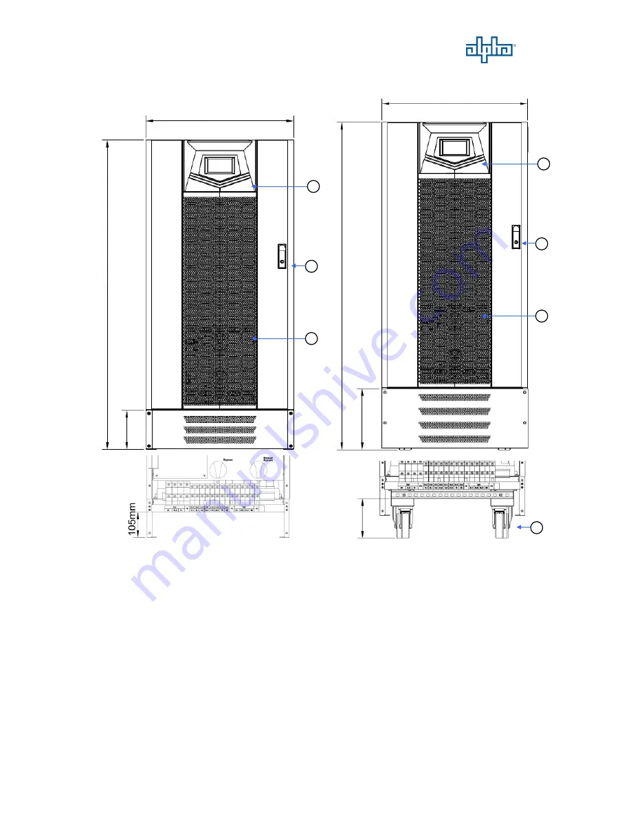
60kVA Front View 

2

3

1

2

3

1

1

5

9

m

m

1

2

5

3

m

m

2

5

1

m

m

1

3

4

5

m

m

600mm

600mm

4

1

6

1

m

m

無 無 無

無 無 無


1. 

Control Panel with Colorful LCD Touch Screen 

3. 

Ventilation Grille 

2. 

Handle with Lock 

4. 

Wheels for Handling 


Wheel Type 

Stationary Type 

(Without Wheel) 

Содержание Tri Power X33 TE

Страница 1: ...Tri Power X33 TE 10 60 kVA UPS Installation and Operation Manual ...

Страница 2: ...ing and Fixing UPS 16 2 3 General Requirement for Ventilation and Maintenance 23 2 4 Power Cables Connections 24 2 5 Communication Cables Connections 33 2 6 UPS Parallel Connections 37 3 Operation Description 42 3 1 Operation Modes 42 3 2 Online Operations 43 3 3 Manual Bypass Operation 43 3 4 Operation Processes 44 4 Control Panel Operation and Function Description 45 4 1 Screen Introduction 45 4...

Страница 3: ...0 60 kVA II 5 Options 50 5 1 Dry Contact Card 50 5 2 RS 485 MODBUS Card 50 5 3 SNMP Card 50 5 4 Temperature Sensor 50 5 5 DC Cold Start Kit 51 5 6 Parallel Communication Cable 51 6 Troubleshooting 52 7 Technical Specification 53 ...

Страница 4: ...ating principles of the UPS and to provide instructions for its safe operation The manual also provides troubleshooting assistance should an abnormal message or behavior occur Should an abnormal message not covered in this manual appear please contact your local authorized service agent for troubleshooting and repair All of the installation operation and maintenance of this device must be performe...

Страница 5: ... must be fully switched off and fully discharged If the UPS is not discharged the UPS will switch to battery power after grid power is disconnected and pose an electrocution hazard 7 Do not place any objects liquid containers or coverings over the UPS The liquid spilt into the UPS or heat prevented from dissipating could lead to internal damage or cause electrocution 8 Make sure that the battery s...

Страница 6: ...This UPS provides Mains input and Bypass input for dual inputs application The system block diagram as shown below 1 Input Switch 5 Inverter 2 Bypass Switch 6 Static Switch 3 Manual Bypass Switch 7 Charger Booster 4 Rectifier 8 Output Switch Load Bypass Input Mains Input Battery Input ...

Страница 7: ... Power X33 TE 10 20 30 40 60 kVA 4 1 2 UPS Outlook View 10 40kVA Front View 1 2 4 3 440mm 1390mm 1 Control Panel with Colorful LCD Touch Screen 3 Ventilation Grille 2 Handle with Lock 4 Wheels for Handling ...

Страница 8: ...Tri Power X33 TE 10 20 30 40 60 kVA 5 10 20kVA Right Side View 1 1 Through Hole for Parallel Communication Cable ...

Страница 9: ...vice Only 5 Terminal Resistor Setting Switch for Parallel Communication 6 Status LED Indictors 7 EPO 8 Backfeed Protection 9 Communication Card Slot2 10 Communication Card Slot1 Please find the detail descriptions of above items on section 2 5 11 Mains Input Switch 14 Output Switch 12 Bypass Input Switch 15 Fuse for Control Power 13 Manual Bypass Switch 16 Battery Tray 9 10 11 13 14 12 15 16 ...

Страница 10: ...60 kVA 7 10 20kVA Rear View 1 2 3 1 2 3 10kVA 20kVA 1 X10 X40 Mains Bypass Input Connections Terminal 1N 2N 1L3 2L3 1L2 2L2 1L1 2L1 2 X50 Output Connections Terminal 3N 3L3 3L2 3L1 3 X20 External Battery Connections Terminal B N B ...

Страница 11: ...Tri Power X33 TE 10 20 30 40 60 kVA 8 30 40kVA Right Side View 1 1 Through Hole for Parallel Communication Cable ...

Страница 12: ...Only 4 USB Port for Service Only 5 Terminal Resistor Setting Switch for Parallel Communication 6 Status LED Indictors 7 EPO 8 Backfeed Protection 9 Communication Card Slot2 10 Communication Card Slot1 Please find the detail descriptions of above items on section 2 5 11 Mains Input Switch 14 Output Switch 12 Bypass Input Switch 15 Fuses for Control Power 13 Manual Bypass Switch 16 Battery Tray ...

Страница 13: ...60 kVA 10 30 40kVA Rear View 3 1 2 3 1 2 30kVA 40kVA 1 X10 X40 Mains Bypass Input Connections Terminal 1N 2N 1L3 2L3 1L2 2L2 1L1 2L1 2 X50 Output Connections Terminal 3N 3L3 3L2 3L1 3 X20 External Battery Connections Terminal B N B ...

Страница 14: ...1 60kVA Front View 2 3 1 2 3 1 159mm 1253mm 251mm 1345mm 600mm 600mm 4 161mm 無 無 無 無 無 無 1 Control Panel with Colorful LCD Touch Screen 3 Ventilation Grille 2 Handle with Lock 4 Wheels for Handling Wheel Type Stationary Type Without Wheel ...

Страница 15: ...Tri Power X33 TE 10 20 30 40 60 kVA 12 60kVA Left Side View 1 Through Hole for Parallel Communication Cable 1 1 Stationary Type Without Wheel Wheel Type ...

Страница 16: ...nals 3N 3L3 3L2 3L1 14 Manual Bypass Switch 15 Fuses for Control Power 1 Parallel Communication Ports 2 HMI Communication Port 3 Communication Selector for Service Only 4 USB Port for Service Only 5 Terminal Resistor Setting Switch for Parallel Communication 6 Status LED Indictors 7 EPO 8 Backfeed Protection 9 Communication Card Slot2 10 Communication Card Slot1 Please find the detail descriptions...

Страница 17: ...w 1 USB Port for Setting Software 4 Output Input Contacts 2 SD Card Slot 5 RS 232 Port for Setting Software 3 External Battery Temperature Connector 6 Communication Port for Remote Panel Please find the detail descriptions of above items on section 2 5 4 4 5 1 2 3 6 6 ...

Страница 18: ...ment with sparks smoke or gas to prevent arcing injury and fire hazards Avoid using dusty materials volatile gases or corrosive substances with a high salt content in the environment where the UPS is installed The installation location of the UPS should be well ventilated During charging the chemical reaction of the battery generates small amounts of gases If there is a crack in the battery then t...

Страница 19: ... This section describes the unpacking and removing processes for wheel type Remove the packing materials and cut straps Remove the cardboard box 10 40kVA 60kVA Unscrew the fastening rail kits on the front and rear side of 10 40kVA and right and left side of 60kVA 10 40kVA 60kVA ...

Страница 20: ...Tri Power X33 TE 10 20 30 40 60 kVA 17 Put 2 fastening rail kits on the pallet edge and make them steady by fastening 4 screws in the pallet 10 40kVA 60kVA ...

Страница 21: ...Tri Power X33 TE 10 20 30 40 60 kVA 18 Raise 2 wheel brakes or expansion foots for remove the UPS from the pallet 10 40kVA 60kVA Wheel Brake Wheel Brake ...

Страница 22: ...Tri Power X33 TE 10 20 30 40 60 kVA 19 Block 2 wheel brakes or adjust the expansion foots to fix the UPS 10 40kVA 60kVA Wheel Brake Wheel Brake ...

Страница 23: ...Tri Power X33 TE 10 20 30 40 60 kVA 20 Floor Fixing for 10 40kVA It is possible to reuse the fastening rail kits to fix the UPS to the floor ...

Страница 24: ...Tri Power X33 TE 10 20 30 40 60 kVA 21 Floor Fixing for 60kVA Stationary Type Without Wheel ...

Страница 25: ...Tri Power X33 TE 10 20 30 40 60 kVA 22 Floor Fixing for 60kVA Wheel Type It is possible to reuse the fastening rail kits to fix the UPS to the floor ...

Страница 26: ...g conditions are met Keep at least 1000 mm of free space in front of the UPS for air flow and future maintenance purposes Keep at least 300mm of free space in rear of the UPS for air flow space Keep at least 500mm of free space in the top of UPS for maintenance operations Front Side 1000mm Rear Side 300mm Top Side 500mm UPS Other Equipment ...

Страница 27: ... 2 4 Power Cables Connections Power Cable Sizing The drawing below shows the positions of power terminals Mains X10 Bypass X40 Output Battery 10kVA Power Terminal Positions Mains X10 Bypass X40 Output Battery 20kVA Power Terminal Positions ...

Страница 28: ...Tri Power X33 TE 10 20 30 40 60 kVA 25 Mains X10 Bypass X40 Output Battery 30kVA Power Terminal Positions Mains X10 Bypass X40 Output Battery 40kVA Power Terminal Positions ...

Страница 29: ...20kVA 20KW 36 A 29 A 69 A 30kVA 30KW 54 A 43 A 103 A 40kVA 40KW 72 A 58 A 137 A 60kVA 60KW 108 A 87 A 206 A 415 V 10kVA 10KW 17 A 14 A 35 A 20kVA 20KW 35 A 28 A 69 A 30kVA 30KW 52 A 42 A 103 A 40kVA 40KW 69 A 56 A 137 A 60kVA 60KW 104 A 83 A 206 A 1 The UPS is operating at rated voltage rated power and batteries are charging but regardless of the overload 2 The UPS is operating at rated voltage an...

Страница 30: ... of cabling is less than 10meters 2 Please over size neutral line N by 1 7 times of the phase line for non linear loads Recommended Circuit Breaker Size Input Output Voltage Output Power Mains Input 1 Output Bypass Input 1 380 V 10kVA 10KW 30 A 25 A 20kVA 20KW 65 A 50 A 30kVA 30KW 95 A 80 A 40kVA 40KW 125 A 105 A 60kVA 60KW 185 A 160 A 400 V 10kVA 10KW 30 A 25 A 20kVA 20KW 60 A 50 A 30kVA 30KW 90 ...

Страница 31: ...Tri Power X33 TE 10 20 30 40 60 kVA 28 Electrical System Connections UPS with single Input Load 3P N UPS with single input and isolation transformer Load 3P 3P N UPS with dual inputs Load 3P N 3P N ...

Страница 32: ... 40 60 kVA 29 UPS with dual inputs and isolation transformer Load 3P 3P N 3P 3P N Load 3P N 3P 3P N Load 3P 3P N 3P N Note You have to install an isolation transformer on one of the inputs if the two power system are different ...

Страница 33: ...Tri Power X33 TE 10 20 30 40 60 kVA 30 UPS in parallel use separate battery Load 3P N UPS in parallel use common battery Load 3P N ...

Страница 34: ...Tri Power X33 TE 10 20 30 40 60 kVA 31 UPS in parallel with output transformer Please do not use separate output transformer for each UPS A common output transformer is recommended Load 3P N Load 3P N ...

Страница 35: ...TE 10 20 30 40 60 kVA 32 Converter Mode Please do not connect the bypass input Load 3P N Load 3P N Note Up to 6 units can be operated in parallel for Converter Mode operation and common battery function is available ...

Страница 36: ... Switch the switch for terminal resistor of parallel communication To ensure good parallel communication quality please set the switch of the two farthest UPS to the ON position Please refer to section 2 6 for detail HMI communication port for control panel This port connects to the LCD display and control panel H U communication selector This switch is to select HMI or USB port Please ensure this...

Страница 37: ...tact to trip the external electromechanical device for isolation from the power circuit The backfeed protection is for ensuring personnel safety against any risk of accidental energy return to the input circuit It imposes the automatic opening of an switching device in case of a malfunction of the static switch Communication Slot1 This slot can install Relay card or RS 485 MODBUS card Communicatio...

Страница 38: ...battery temperature sensor Please refer to section 5 4 SW2 When Relay card is installed in Slot2 please switch to Slot position When SNMP card is installed in Slot2 please switch to SNMP position SW3 the switch for terminal resistor of parallel communication To ensure good parallel communication quality please set the Switch of the two farthest UPS to the ON position Please refer to section 2 6 fo...

Страница 39: ...t NC NO for each output contact To short the input contact for send a command to UPS The user can change the definition for each contact please contact the local authorized service agent to change the setting RS 232 Pin Assignment 1 2 3 4 5 6 7 8 9 Baud Rate 57600bps Data Length 8 bits Stop Bit 1 bit Parity None This port is available for change the setting of UPS by setting software 2 TX OUT 3 RX...

Страница 40: ...llel operation system Parallel configuration must be performed by authorized and qualified technicians who are familiar with this UPS Parallel communication cables are requested to connect to UPS each other Please only use the parallel communication cables which are supplied with UPS manufacturer for ensure UPS can operate correctly in a parallel configuration The parallel communication cables mus...

Страница 41: ...Tri Power X33 TE 10 20 30 40 60 kVA 38 When installing the parallel communication cables please let the parallel communication cable through the hole at side of UPS as shown below ...

Страница 42: ...Tri Power X33 TE 10 20 30 40 60 kVA 39 Recommended 1 1 parallel system configuration Mains Load Mains Bypass Load 1 1 parallel Single Input 1 1 parallel Dual Input Parallel Communication Cables ...

Страница 43: ...Tri Power X33 TE 10 20 30 40 60 kVA 40 Recommended N 1 parallel for single input system configuration Up to 6 UPS Units Load Mains External Manual Bypass Switch Parallel Communication Cables ...

Страница 44: ...Tri Power X33 TE 10 20 30 40 60 kVA 41 Recommended N 1 parallel for dual input system configuration Up to 6 UPS Units Load Mains External Manual Bypass Switch Bypass Parallel Communication Cables ...

Страница 45: ...gh Rectifier following the same setup as VFI Mode Inverter is also kept ready to switch power supply modes at any time If VFI mode is set then power can be quickly routed from Bypass to Inverter Attention In ECO Mode the power supply frequency and voltage will be less stable Please check the load requirements and use ECO Mode with care 3 Converter Mode Converter Mode allows the user to provide a p...

Страница 46: ...re or module overheating the power supply circuit switches from Inverter to the bypass output 3 Battery Mode When the UPS detects a failure in the main power supply then power is provided from the battery instead The touch screen at the front of the module will also display current battery level to remind the user 3 3 Manual Bypass Operation When the manual bypass switch is activated the load is p...

Страница 47: ...2 Cold Start 1 User can start up UPS by battery when main input power is not available 2 Select Command Operation Cold start precharge ready on LCD display 3 Select Normal mode to start UPS 3 4 3 Shutdown 1 Select Command Operation Shutdown on LCD display 3 4 4 Switch to bypass 1 Select Command Operation Shutdown converter except bypass on LCD display 2 The Inverter will be shutdown and bypass wil...

Страница 48: ...t output voltage frequency current and battery information from the touch panel Please refer to below section for learn more detail information and functions of the LCD touch panel 4 1 Screen Introduction A Display current time status and information of UPS B Indicate Single or Parallel system and select the desire UPS unit to check the information Single Unit Parallel System C Click here to see t...

Страница 49: ...cture Slide the screen to switch to other menu page and click the menu icon to enter to the desire function Click to hide show the sub menu The button below will appear on some function pages Button Function Click it to save the new setting Click it to reload the data Click it to go to Mimic Display ...

Страница 50: ...lear latch alarm and buzzer Other Recover backfeed protection signal Battery Test Monitor Identification Display UPS information Real Time Information Display real time measurements of input output bypass and battery Maintenance Code Display the maintenance code for technician to check the status of the UPS Version Disply the control MCU software and firmware version Configuration Alarm Set alarm ...

Страница 51: ...touch display General Set the turn off time of LCD backlight Date and Time Set date and time Peripherals 1 Set communication card Event Log Display the event log list of UPS Log on Load Display the history curve of loading Up to 7 days data Permission Setting Login Logout Login with the password 2 Password Modification 1 Chang user password Maintenance 1 Screen Calibration Calibrate the touch scre...

Страница 52: ...surements will have red background Click D E F to change the measure parameter and press for 3 second to enter to Real Time Information G display the status of battery Press it for 3 second to enter to Real Time Information The battery isn t connected The green pattern indicates the battery is charging The yellow pattern indicates the battery is discharging H Alarm silence button Click it to silen...

Страница 53: ...These contacts are programmable and user can change the definition for each contact Please refer to Dry Contact Card manual for more detail 5 2 RS 485 MODBUS Card RS 485 ports with JBUS MODBUS protocol Please refer to RS 485 Card manual for more detail 5 3 SNMP Card This is the Ethernet network card with TCP IP HTTP and SNMP protocols ...

Страница 54: ...up by the battery without mains input 5 6 Parallel Communication Cable The parallel communication cables are required when UPS in parallel Each UPS provides a 1 5 meters parallel communication cable as standard and it can use for 2 UPS in parallel A longer parallel communication cable is available for more UPS in parallel 3000 0mm 4 3mm 7 2mm ...

Страница 55: ...t there is a problem with the UPS Click to have a alarm list as below picture We recommend checking the error code using the following method when troubleshooting Click Information Maintenance Code to bring up the screen shown below If you can provide the maintenance code to the authorized distributor this will speed up troubleshooting You also can click Export to save the maintenance code in SD c...

Страница 56: ...tage Harmonic Distortion 1 with linear load 3 with distorting load Overload 110 for 60 minutes 125 for 10 minutes 150 for 1 minutes Parallel Up to 6 units Bypass Voltage 380 400 415V 3 Phase N Voltage Tolerance Preventive range 10 Adjustable 5 15 Critical range 25 Adjustable 16 30 Frequency 50 60Hz Frequency Tolerance 1Hz 3Hz Selectable Battery Number of batteries 12V 32 34 36 38 40pcs configurabl...

Страница 57: ...1390 Wheel type 600 x 827 x 1253 w o wheel 600 x 827 x 1345 Wheel type Weight 84 kg 86 kg 130kg 132kg 194kg w o wheel 200kg Wheel type Protection Grade IP20 Color RAL 7016 Anthracite Grey Environment Storage Temperature 20 70 Storage Humidity 95 Operation Temperature 0 40 Operation Humidity 0 95 w o condensation Operating Altitude 1000 m without derating 1 Tested to standards LVD EN62040 1 EMC req...

Страница 58: ...Tri Power X33 TE 10 20 30 40 60 kVA 55 ...

Страница 59: ...10 20 30 40 60 kVA 56 CONTACT INFORMATION 192321262006003 Alpha Technologies GmbH www alphatechnologies com Hansastrasse 8 91126 Schwabach Germany Tel 49 0 9122 79889 0 Fax 49 0 9122 79889 21 sales alphatechnologies de ...

Отзывы: