


507788-01
Issue 2007
Page 8 of 20
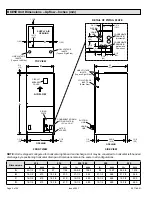
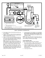
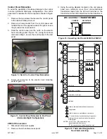
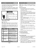
ABOVE
FINISHED
SPACE?
OVERFLOW DRAIN LINE
ALWAYS RUN AN OVERFLOW DRAIN LINE. IF NOT POSSIBLE TO
ROUTE OVERFLOW DRAIN LINE, INSTALL LOW VOLTAGE
OVERFLOW SWITCH KIT. WIRE KIT TO SHUT DOWN
COMPRESSOR PER INSTRUCTIONS.
NO
YES
PART #
X3169
CLEAN OUT
VENT
PRESS IN
(DO NOT GLUE)
VENT MUST EXTEND
ABOVE HEIGHT OF
COIL DRAIN PAN BY
TWO INCHES (51MM)
1” X 3/4” X 3/4”
REDUCING
TEE WITH
PLUG
1
P-TRAP
49P66, J-TRAP #
91P90 OR ANY
PVC SCH 40 P- OR
J-TRAP 3/4”
OVERFLOW
DRAIN
AIR HANDLER DRAIN PAN
WHEN A COIL IS LOCATED ABOVE A FINISHED SPACE, A
3/4” (19.1MM) SECONDARY DRAIN LINE MUST BE:
CONNECTED TO SECONDARY DRAIN PAN
OR
CONNECTED TO THE OVERFLOW DRAIN OUTLET OF
THE AIR HANDLER DRAIN PAN.
TRAPS MUST BE DEEP ENOUGH TO OFFSET MAXIMUM STATIC DIFFERENCES —
GENERALLY, TWO INCHES (51MM).
DRAIN LINE SHOULD
SLOPE A MINIMUM OF
ONE INCH PER 10
FEET (25MM PER 3
METERS)
NOTE
— WHEN A AIR HANDLER IS LOCATED
ABOVE A FINISHED SPACE THE SECONDARY
DRAIN PAN MUST HAVE A LARGER FOOTPRINT
THAN THE AIR HANDLER.
MAIN
DRAIN
TO APPROVED
DRAIN
FOR NEGATIVE PRESSURE COILS (BLOWER
AFTER COIL) TRAPS ARE REQUIRED ON ALL
DRAIN LINES CONNECTED TO COIL.
COMPACT OVERFLOW SWITCH WITH 3/4” FEMALE SLIP INLET
AND MALE ADAPTER, TWO PART DESIGN FOR USE WHERE
OBSTRUCTIONS PREVENT DIRECT THREADING
SECONDARY
DRAIN PAN
2”
(51MM)
TRAP DEPTH
1
P-TRAP 49P66 REQUIRES A LARGER INSTALLATION SPACE THAN THE J-TRAP 91P90.
2
PIPE NIPPLE PROVIDED IN BAG ASSEMBLY - SCH 80, 3/4” I. D. X 5” - 34K7401 (1): CUT THE PIPE IN HALF AND USE IT TO ROUTE THE MA IN DRAIN.
MAIN
DRAIN
PROVIDED
PIPE NIPPLE
2
CUT TO
REQUIRED
LENGTH
SIDE VIEW
Figure 8.
Typical Main and Overflow Drain
7. Route the drain line to the outside or to an appropriate
drain. Drain lines must be installed so they do not block
service access to the front of the air handler. A 24”
clearance is required for filter, coil, or blower removal
and service access.
NOTE:
Check local codes before connecting the drain line
to an existing drainage system. Insulate the drain lines
where sweating could cause water damage.
Test Condensate Drain
Test the drain pan and drain line after installation:
1.
Pour several quarts of water into drain pan. Use
enough water to fill both the drain trap and the line.
2. Check the installed drain pan. Drain pan must be
draining completely. Drain line fittings must not be
leaking. Water must be draining from the end of the
primary drain line.
3. Correct any leaks found.
4. Check again to ensure drain ports and drain pan are
free of all debris.
5. Plug and check any unused drain pan openings for
tightness. Torque plugs to 36 in. lb. to prevent water
leaks or seepage from the drain pan.
6. Install a 2” trap in the main (primary) drain lines as
close to the unit as practical (see Figure 8). Make sure
the top of the trap is below the connection to the drain
pan to allow complete drainage of the pan.
NOTE:
Horizontal runs must have an anti-siphon air
vent (standpipe) installed ahead of the horizontal run.
See Figure 8. An extremely long horizontal run may
require an oversized drain line to eliminate air traps.
NOTE:
Do not operate air handler without a trap in
the main (primary) drain. The condensate drain is on
the negative pressure side of the blower; therefore, air
being pulled through the condensate line will not allow
positive drainage without a proper trap.


