background image

10

45-074, REV. 5/18

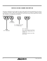
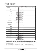
3.15 Industry Standards

ANSI/ITSDF B56.1-2016 is the published sequence and 
direction standard for lever- and hand-type controls. 

The chart on the following page shows 
industry standards. Your equipment may 
be different. If you do not routinely operate 
this equipment, refresher training is 
recommended. You must reacquaint 
yourself with this manual and the equipment 
before starting, and then proceed slowly.

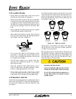
Special controls such as automatic devices should be 
identified, preferably according to the recommendations 
in Figure 3-6.

When a function is controlled by a pair of push buttons, 
they should operate in the same sense as the lever con-
trols. For example, pushing a button located to the rear 
(relative to the operator’s position) should serve the same 
function as moving a control lever to the rear.

3.16 Clamp Open Control

Effective October 7, 2010, safety standard ANSI/ITSDF 
B56.1, Section 7.25.7 covers all lift trucks with a load 
bearing clamp (paper roll clamp, carton clamp, etc.), 
and requires the driver to make two distinct motions 
before opening or releasing the clamp. For example, 
you must press a switch and then move a lever to 
unclamp the load. This requirement applies to new 
and used attachments being mounted on trucks which 
shipped from the factory after October 7, 2010, and is a 
recommended feature to be installed on dealer orders 
and existing applications.

Содержание Long Reach PTC Series

Страница 1: ...1 45 074 REV 5 18 Installation Maintenance and Service Manual PTC Pipe Clamp...

Страница 2: ...10 3 16 Clamp Open Control 10 SECTION 4 INSTALLATION PROCEDURE 12 4 1 Truck Requirements 12 4 2 Attachment Installation 12 4 3 Hydraulic Connections 13 SECTION 5 SERVICE PROCEDURE 14 5 1 Attachment Re...

Страница 3: ...h nameplate upper left corner on the body Record the information from the nameplate along with the date received at the bottom of this page If the nameplate is missing look for the serial number stamp...

Страница 4: ...is equipped The guide below illustrates the information that is represented in its model number Always include model and serial number when ordering parts or requesting service information Series Mod...

Страница 5: ...ne Because of special condi tions your company s material handling procedures may be somewhat different from those shown in this manual 3 3 Safety Symbols The following terms define the various precau...

Страница 6: ...nnel Safety When removing or installing dismountable at tachments always keep hands and feet free from dangerous positions or pinch points Never leave a dismounted attachment in a dangerous position K...

Страница 7: ...piece of cardboard to check for hydraulic leaks Wear personal protective equipment such as gloves and safety glasses whenever servicing or checking a hydraulic system Assume that all hydraulic hoses a...

Страница 8: ...par tially loaded Equipment overload hazard Injury or equipment damage may result if the capacity of the truck and attachment combined are less than the attachment capacity Consult truck nameplate fo...

Страница 9: ...slowly around corners Sound horn on blind corners Be careful of tail swing and overhead clear ances Watch in all directions Avoid sudden stops 3 14 Operator s Controls Some lift trucks are equipped w...

Страница 10: ...uttons they should operate in the same sense as the lever con trols For example pushing a button located to the rear relative to the operator s position should serve the same function as moving a cont...

Страница 11: ...ft Rearward or up Forward or down Slope Clockwise Counterclockwise Rearward or up Forward or down Fork position Together Apart Rearward or up Forward or down Trip Engage Release Rearward or up Forward...

Страница 12: ...imensionsshowninANSI ITSDF B56 11 4 2013 2 Make sure the truck carriage is clean conforms to ANSI recommendations and the notches are not damaged 3 The truck hydraulic system must supply the attach me...

Страница 13: ...ipment 4 3 Hydraulic Connections 1 Install the lines from the truck s hydraulics to the hydraulics of the attachment 2 Inspect installation to ensure hoses are not kinked or pinched between the truck...

Страница 14: ...agement of attachment from truck 4 To reinstall follow the installation procedure in this manual NOTICE Equipment damage hazard Equipmentdamageandlossofperformance could result if air is trapped in th...

Страница 15: ...ATION LINE as the seal is installed Separation Line Seal Seal Separation Line Figure 5 2 Bearing Seal 5 Insert the seal into the groove with firm steady pres sure but avoid stretching the seal 6 Thele...

Страница 16: ...p plug hole allowing traped air to escape through the back plug hole until grease is present in the back plug hole 4 To fill gearbox mounted to back plate fill gearbox from the back plug hole allowing...

Страница 17: ...ctite CAUTION Oil leak hazard Removing the adapter plate without draining the oil can result in a large oil spill Drain oil from the gearbox before removing the adapter plate 5 Remove the capscrews fr...

Страница 18: ...em loose Figure 5 13 Capscrew Capscrew O Ring O Ring Motor Adapter End Cap Shim Shim Shim Coupling Figure 5 13 End Cap Motor Adapter 10 Remove the input shaft assembly The assembly fits tightly so use...

Страница 19: ...rom the housing Figure 5 16 Equipment damage hazard Impact wrenches could damage screws or sockets if screws have been secured with Loctite Use care when working with the gear assembly Do not use a im...

Страница 20: ...toradapter Makenote of any installed shims Capscrews are installed with Loctite so use a long handled wrench to break them loose Use a large screwdriver and hammer to sepa ratethewormcapfromthehousing...

Страница 21: ...applicable NOTICE Use Loctite Blue on all capscrews See Section 7 for Torque Specifications 4 Place the bearing cones on both ends of the worm gear shaft and install into the housing 5 Press on the be...

Страница 22: ...e seal on the end cap can now be serviced Figure 5 23 End cap Capscrew Seal Washer Figure 5 23 End Cap 4 Remove the gerotor and the drive spacer if appli cable The seal on the gerotor can now be servi...

Страница 23: ...ea of the housing where the capscrew enters Figure 5 27 Be careful not to overheat the housing and damage the motor Apply heat for 8 to 10 seconds while gradually applying torque to the capscrew with...

Страница 24: ...h either seals 12 A metal plug with seal plugs a machining hole in the housing It is not necessary to remove the plug and replace seal unless leakage occurs around the plug To remove the plug insert a...

Страница 25: ...the end of the plug Push the plug into the housing so the plug and housing are flush Be careful not to damage the seal 4 Lubricatetheoutputshaftwithhydraulicoil theninstall the output shaft into the h...

Страница 26: ...hose for assembly Wipe off excess Loctite from the housing face using a non petroleum base solvent NOTICE Do not apply Loctite to threads more than 15 minutes before installing capscrews If the housin...

Страница 27: ...shaft cavity 17 Install73mm 2 875in I D sealintothehousingseal groove Avoid twisting the seal 18 Installthedrive Useafelt tipmarkertomarkonedrive tooth Align this tooth with the timing dot on the shaf...

Страница 28: ...nders several times to bleed out trapped air CAUTION Equipment damage hazard Equipmentdamageandlossofperformance could result if air is trapped in the hydraulic system Activate the hydraulic functions...

Страница 29: ...areful not to scratch the seal grooves Cut the seals to remove them from the pis ton Figure 5 44 Figure 5 44 Seal Removal 8 Usethesameprocedureasabovetoremovetheseals from the gland cap 5 12 Cylinder...

Страница 30: ...the seal should be facing the piston Figure 5 46 Locknu Pisto Cylinder Rod Gland Cap Wiper Ring Seal O Ring Backup Ring Figure 5 46 Gland Cap Seal 4 Install the piston on the rod and tighten the lock...

Страница 31: ...vel assembly ports P1 P2 P3 P4 P5 P6 P7 and P8 4 Disconnect the motor hydraulic hoses at the swivel assembly ports A and B 5 Remove the swivel assembly mounting bolts and remove 5 16 Swivel Assembly I...

Страница 32: ...100 Hour Maintenance 1 Greasetheringgearbearingassembly SeeSection 5 2 SECTION 6 MAINTENANCE 500 Hour Maintenance 1 Inspectarmsandmountinghooksforcracks orwear Ifanydefectisfound removefromserviceforr...

Страница 33: ...1 1 8 1 305 1 1 4 1 640 1 1 4 1 010 1 1 4 1 840 1 3 8 2 150 1 3 8 1 330 1 3 8 2 415 1 1 2 2 850 1 1 2 1 760 1 1 2 3 205 Grade 5 Grade 8 Socket Head Capscrew Figure 6 1 Fastener Identification Figure 6...

Отзывы: