


16
45-074, REV. 5/18
Equipment damage hazard.
Overfilling the gearbox may damage the
gearbox, causing a leak.
Do not overfill gearbox with oil.
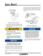
3. Fill the gearbox to the oil level plug location.
4. The oil level should be checked occasionally at the
oil level plug. If the oil level has dropped, a leak may
have occurred. The leak should be corrected and the
oil should be leveled off to the oil level plug location.
5. Reinstall plugs.
Part Number: YGC-48, YGC-49, YGC-49-LH, YGC-50
And YGC-50-LH
1. The grease in the gearbox will not need to be filled or
changed unless the Gearbox itself has been serviced.
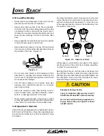
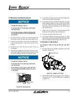
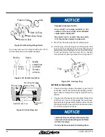
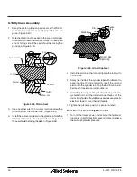
2. Remove the top and back plugs from the gearbox and
completely fill with Movilux EPO or equivalent grease.
(Figure 5-6)
Top Plug
Back Plug
Figure 5-6, Gearbox Grease Plugs
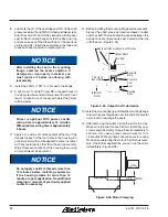
3. Lay the gearbox with the pinion gear down and fill the
gearbox from the top plug hole, allowing traped air
to escape through the back plug hole, until grease is
present in the back plug hole.
4. To fill gearbox mounted to back plate, fill gearbox
from the back plug hole, allowing traped air to escape
through the top plug hole, until grease is present in
the top plug hole.
5. Reinstall the plugs.
5.5 Gearbox Disassembly
Part Number: YGC-29, YGC-32, YGC-43 And YGC-
43-LH
1. Remove the attachment from truck. (See Section 5.1)
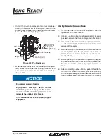
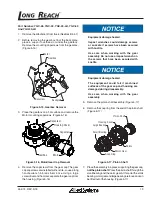
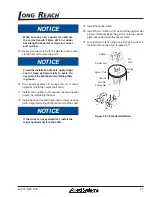
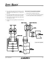
2. Before removing the gearbox from the back plate,
place a support overhead or under the gearbox.
Remove the mounting capscrews from the gearbox.
(Figure 5-7)
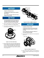
3. Place the gearbox on a flat surface and remove the
Motor mounting capscrews. Note: Coupling fits loose
and may slide out. (Figure 5-8)
4. Remove the Pinion Gear and Key from the Output
Shaft. Use a screwdriver to knock loose the key.
Gearbox
Capscrew
Motor
Back Plate
Figure 5-7, Gearbox Removal
3. Place the gearbox on a flat surface and remove the
motor mounting capscrews. Note: Coupling fits loose
and may slide out. (Figure 5-8)


