


15
45-074, REV. 5/18
5.3 Bearing Seal Replacement
Equipment damage hazard.
Foreign matter in the bearing could cause
bearing failure.
Prevent any foreign matter from falling into
the bearing during the seal replacement
procedure.
1. Remove all traces of the former seal and glue from
the seal groove by mechanically scraping the groove.
2. Clean the groove with a no-residue commercial sol-
vent (trichloroethane) to remove any trace of oil or
grease.
3. Wipe the seal with the same solvent to insure
cleanliness.
4. Apply a bead of adhesive to the back of the seal groove.
Use enough adhesive to cause some extrusion to coat
the seal on all three surfaces contacting the groove.
Equipment damage hazard.
Foreign matter in the bearing could cause
bearing failure.
Keep adhesive from being extruded into
the bearing SEPARATION LINE as the seal
is installed.
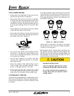
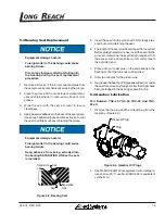
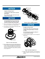
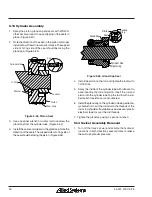
Separation
Line
Seal
Seal
Separation
Line
Figure 5-2, Bearing Seal
5. Insert the seal into the groove with firm steady pres-
sure, but avoid stretching the seal.
6. The length of the seal provided is longer than required.
Before gluing the last six inches, insert the seal into the
groove to determine the exact length required. Trim
the excess with a sharp knife so it smoothly meets
the adjoining end.
7. Place a drop of super-glue on the end already in the
bearing so that the two ends will be joined.
8. Allow ten minutes for the glue to cure.
9. Re-grease the bearing until grease exudes from under
the seal to remove any foreign matter that might have
become lodged in the bearing separation line.
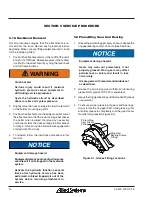
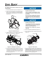
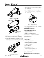
5.4 Gearbox Lubrication
Part Number: YGC-29, YGC-32, YGC-43 And YGC-
43-LH
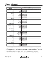
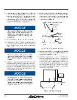
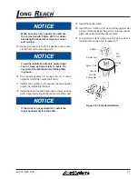
1. Remove the top plug and the oil level plug from the
Gearbox. (Figure 5-3)
Plug
Oil Level Plug
Figure 5-3, Gearbox Oil Plugs
2. Use Mobil HD 85W140 or equivalent oil. For tempera-
tures below -20° F, use Mobil SHC 634 or equivalent
synthetic oil.


