background image

45-009  REV. 8/20

9

•  Always operate an attachment from the operator’s seat, never while standing next 

to the lift truck.

•  Do not allow riders on the truck at any time.

•  Always use reverse when carrying a load that impedes full vision. Watch for pedes-

trians when transporting. 

•   Always use personal protective equipment (PPE) appropriate to the situation. 

3.7 Pre-start Checks

•  Check your equipment before you operate it. If anything looks wrong, unusual or 

different, report it before using the attachment.

•  Do not operate this machine if you know of malfunctions, missing parts, and/or mis-ad-

justments. These situations can cause or contribute to an accident or damage to the 
machine. Stop the machine immediately if problems arise after starting.

•  Check to make sure the attachment on your truck is the same as on the truck capacity 

plate.

•  Check for hydraulic leaks and cracked hoses or fittings. Check the hydraulic oil level 

in the lift truck hydraulic reservoir.

•  All electrical cables and connectors must be in good condition. Use caution in wet 

weather to avoid danger from electrical shock. 

•  Always check the attachment for proper fit and engagement of the truck carriage.

3.8 Operation Warnings

•  You must be trained to operate this equipment prior to operation. Be extremely careful 

if you do not normally operate this machine. Reorient yourself to the machine before 
starting, then proceed slowly.

•  Always operate an attachment from the driver’s seat.

•  Always lower the attachment if you need to leave the lift truck. A lift truck supporting 

a load requires your full attention.

3.9 Hydraulic Hazards 

DANGER

Injection hazard.

Infection and gangrene will result when hydraulic oil 
penetrates the skin. See a doctor immediately to prevent 
loss of limb or death. 

Use a piece of cardboard to check for hydraulic leaks.

Содержание LONG REACH FLN Series

Страница 1: ...Installation Maintenance and Service Manual FLN and FLS Heavy Duty Fork Positioners REV 8 20 45 009 ...

Страница 2: ...45 009 REV 8 20 THIS PAGE WAS INTENTIONALLY LEFT BLANK ...

Страница 3: ...1 Truck Requirements 17 4 2 Attachment Installation 18 4 2 1 Installations with Bolt On Hooks 19 4 2 2 Installations with Quick Hooks 21 4 2 3 Installations with Sideshift 21 4 2 4 Lower Roller Assemblies Sideshift Units Only 22 4 3 Fork Cylinder Anchor Some FLS and FLN Models 23 4 4 Fork Installation Instructions 23 4 4 1 Narrow Fork 24 4 4 2 Wide Fork 24 4 5 Hydraulic Connections 24 SECTION 5 MA...

Страница 4: ...r attachment locate the Long Reach nameplate upper left corner on the body Record the information from the nameplate along with the date received at the bottom of this page If the nameplate is missing look for the serial number stamped directly into the metal at the nameplate location and consult the factory for details ...

Страница 5: ... 50 725 72 50 745 74 50 780 78 00 785 78 50 DESIGN C Weld on fork installation D No weld fork carriers DESIGN DESIGN E No weld F Weld on fork G No weld MOUNTING CLASS A ITA II B ITA III C ITA IV MOUNTING CLASS A ITA II B ITA III C ITA IV Note Weld Weld cylinder anchor on the back of fork No weld Supplied fork carrier Note Weld Weld cylinder anchor on the back of fork No weld Supplied fork carrier ...

Страница 6: ...s your responsibility to see that they are carried out 3 2 Safety Regulations Know your company s safety rules Some companies have site specific directions and procedures The methods outlined in your operator s manual provide a basis for safe oper ation of the machine Because of special conditions your company s material handling procedures may be somewhat different from those shown in this manual...

Страница 7: ...tachment If the truck is equipped with front end attachments other than factory installed attachments truck must be marked to iden tify the attachments and show the approximate weight of the truck and attachment combination at maximum elevation with load laterally centered 3 5 Training Make sure all operators are trained in the fork and attachment adaptation operation and use limitations Retrain a...

Страница 8: ...as Never jump on or off the machine Never stand on top of material being raised lowered or transported Figure 3 1 Figure 3 1 Figure 3 2 Figure 3 3 Never use the attachment or its load to support a man carrying device Never allow anyone under a load or under the carriage Figure 3 2 Never stand in front of or beside an attachment that is being operated Never allow another person to approach an attac...

Страница 9: ...on the truck capacity plate Check for hydraulic leaks and cracked hoses or fittings Check the hydraulic oil level in the lift truck hydraulic reservoir All electrical cables and connectors must be in good condition Use caution in wet weather to avoid danger from electrical shock Always check the attachment for proper fit and engagement of the truck carriage 3 8 Operation Warnings You must be train...

Страница 10: ...l shock Never attempt electrical testing or repair while standing in water Do not wear electrically conductive jewelry clothing or other items while working on the electrical system 3 11 Maintenance Warnings Maintenance lubrication and repair of this machine can be dangerous unless performed properly You must have the necessary skills and information proper tools and equip ment Work in a method th...

Страница 11: ...ting your skin can be fatal WARNING Suffocation hazard Engine exhaust fumes can cause death Remove the exhaust fumes from the area with an exhaust pipe extension or use ventilation fans and open shop doors to provide adequate ventilation Before disconnecting hydraulic lines be sure to lower all loads and relieve all hydraulic pressure The load could fall on you or escaping hydraulic oil could caus...

Страница 12: ...junction with an attachment for load handling Never clamp loads other than what the attachment was designed to handle Always carry cylindrically shaped loads in the vertical position not the horizontal Always clamp loads with the contact pads if applicable not the arm or arm base Never rotate a load that is off center to the centerline of rotation Severe damage to the rotator could result Always e...

Страница 13: ... around corners Sound horn on blind corners Be careful of tail swing and overhead clearances Watch in all directions Avoid sudden stops 3 14 Operator s Controls Some lift trucks are equipped with a single lever to control both hoist and tilt functions others have separate levers for each function Refer to your lift truck manual for more information For clarity the direction of arm movement is show...

Страница 14: ...refresher training is recommended You must reacquaint yourself with this manual and the equipment before starting and then proceed slowly Special controls such as automatic devices should be identified preferably according to the recommendations in Figure 3 6 When a function is controlled by a pair of push buttons they should operate in the same sense as the lever controls For example pushing a bu...

Страница 15: ...ad damage may result if a fork positioner attachment is used to clamp a load The fork positioner does not have enough clamping force to safely hold a load Always support the load with the forks Do not use fork positioning attachments as clamps Figure 3 6 Do Not Clamp ...

Страница 16: ...ft Rearward or up Forward or down Slope Clockwise Counterclockwise Rearward or up Forward or down Fork position Together Apart Rearward or up Forward or down Trip Engage Release Rearward or up Forward or down Grip Engage Release Rearward or up Forward or down Truck stabilizer Raise Lower Rearward or up Forward or down Clamp Clamp Release Rearward or up Forward or down For high lift order picker tr...

Страница 17: ...stallation of the required valving at the truck factory The attachment model description found on your shipped invoice will state the following truck requirements flow gpm psi and minimum truck carriage width Recommended hydraulic supplies are as follows Min Max PSI Class II 3 2 4 1 2 200 3 000 Class III 2 9 6 4 2 200 3 000 Class IV 4 0 12 0 2 200 3 000 1 The truck carriage must conform to the Ame...

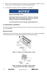
Страница 18: ...iginal attachment Consult with factory before altering original equipment 4 2 Attachment Installation There are two kinds of hooks bolt on and quick hook Follow the directions for the hook on your attachment Bolt On Hooks Remove the lower bolt on hooks and if applicable make a note of any factory installed shims Shims are used to create space between the hook and carriage Bottom Bar Bottom Hook Sp...

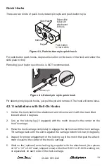
Страница 19: ...tallations with Bolt On Hooks 1 Center the truck behind the attachment and drive toward it with the mast tilted forward about 4 degrees 2 Line up the locking lug if equpped with the notch closest to the center on the truck s carriage 3 Raise the truck carriage completely to engage the top hooks with the truck carriage Tilt carriage back until the unit is against the carriage bottom fork bar 0 degr...

Страница 20: ... them up or down so the clearance is no more than 3 32 On Class II and Class lll units tighten the 3 8 bolts to 33 ft lbs On Class lV units tighten the 1 2 bolts to 77 ft lbs On units using 9 16 UNC bolts tighten the bolts to 112 ft lbs Notice Make note of any factory installed spacers or shims Shims are used to create clearance between the hook and carriage Maximum Clearance 1 8 Maximum Clearance...

Страница 21: ... the truck carriage prevents the slide plate from being raised up high enough install shims between the attachment and the body of the quick hooks 4 2 3 Installations with Sideshift 1 Center the truck behind the attachment and drive toward it with the mast tilted forward about 4 degrees 2 Place the midplate onto the ITA bar Make sure it is seated all the way down on the bar Make sure the locking l...

Страница 22: ...013 welding rod or equivalent on each side of the truck carriage 4 2 4 Lower Roller Assemblies Sideshift Units Only 1 Move the attachment away from the carriage about two inches Place a block between the attachment and the carriage to hold it in position 2 Place the rollers anywhere in the heel plate pockets on the lower right and left hand sides of the attachment They are a loose fit and do not n...

Страница 23: ...ance 3 32 Shim as Required Bottom Bar Bottom Hook Fork Base Truck Mast Roller Assembly Figure 4 10 Adjusting sideshifting lower bolt on hook assembly 4 3 Fork Cylinder Anchor Some FLS and FLN Models 1 Refer to the parts documentation that came with your attachment for fork cylinder anchor location for your forks Make sure cylinder is parallel to carriage weldment NOTICE Cylinder anchors are shippe...

Страница 24: ...re connecting the truck hydraulic system to the attachment the system must be purged through the filtration system This will eliminate any contamination that might exist in the auxiliary hydraulic system of the truck 2 Purge the system by installing a jumper line and operating each hydraulic func tion clamp rotate and side shift if equipped in each direction for a minimum of 30 seconds Figure 4 11...

Страница 25: ... cylinder base end To cylinder base end C4 C3 C2 C1 To cylinder rod end To cylinder rod end To truck supply close V1 To truck supply open V2 V3 V4 To truck secondary side shift Figure 4 13 Hose connections Open Forks Port V2 Close Forks Port V1 Figure 4 14 Hose connections ...

Страница 26: ...he arms all the way Now check that the truck s hydraulic oil reservoir level is at the recommended level 7 Before placing the attachment in operation check the following A Inspect all hoses and fittings for leaks and routing clearance Be sure to include clearance of jumper hoses to the mast B Check the valve and cylinder for leaks C Check cotter pins at each end of the cylinder for security 8 Afte...

Страница 27: ...and shank must be throughly checked for wear especially near the heel If heel thickness is reduced to 90 of the original replace the fork 100 Hour Maintenance 1 Complete the above daily checks 2 Check all hoses and fittings for wear or damage Inspect for hydraulic leaks 3 Check for loose or missing bolts 4 Check wear on the bronze top hooks Bronze top hooks should be replaced when the clearance be...

Страница 28: ... GRADE 8 COARSE THREAD GRADE 5 COARSE THREAD SOCKET HEAD COARSE THREAD Bolt Size Lubricated Torque Bolt Size Lubricated Torque Capscrew Size Lubricated Torque 1 4 11 ft lbs 1 4 7 5 ft lbs 1 4 12 5 ft lbs 5 16 23 5 16 16 5 16 26 3 8 40 3 8 28 3 8 46 7 16 63 7 16 45 7 16 74 1 2 96 1 2 68 1 2 115 9 16 140 9 16 98 9 16 160 5 8 195 5 8 140 5 8 215 3 4 340 3 4 240 3 4 385 7 8 550 7 8 390 7 8 615 1 820 1...

Страница 29: ...c valve ports V1 and V2 Figure 6 1 Cap hoses to prevent contamination and tag for reassembly Valve Flow Relief Truck Connection Port V2 Truck Connection Port V1 Port C3 S Port C2 From C2 From C1 From C3 Port C1 Figure 6 1 Hydraulic Connection Right Hand Terimination Standard 3 Disconnect the sideshift connections if applicable Cap hoses to prevent contami nation and tag for reassembly 4 Slightly r...

Страница 30: ...ydraulic system Activate the hydraulic functions several times after hydraulic service has been performed to bleed trapped air out of the system before returning attachment to service 6 2 Cylinder Removal 1 Remove the cylinder rod end cotter pin and clevis pin 2 Disconnect the hydraulic connections Cap hoses to prevent contamination and tag for reassembly 3 Remove cotter pin and clevis pin at the ...

Страница 31: ...the rod to prevent scarring Figure 6 4 Figure 6 4 Cylinder Shaft 7 Remove the piston retaining nut and remove the piston Figure 6 5 Piston Nut Piston Gland Cylinder Head Lock Nut Ring Retaining Ring Figure 6 5 Rod Assembly 8 Carefully pry up on the piston seals using a blunt tip screw driver being careful not to scratch the seal grooves Cut the seals to remove from the piston Figure 6 6 Figure 6 6...

Страница 32: ... of the barrel Inspect the piston for 1 Scratches or nicks on seal grooves 2 Wear on O D Inspect the cylinder rod for 1 Scratches or nicks on the rod surface 2 Straightness of the rod 3 Damaged threads Inspect the gland cap for 1 Scratches or nicks in seal grooves 2 Damaged threads or spanner wrench holes 3 Excessive wear in bore Replace any component found to be defective ...

Страница 33: ...s and wipers in the gland cap Note the direction of the seals The cupped side or O ring side of the seal should be facing the piston Figure 6 8 Refer to your parts manual for information specific to your model Wiper ring Lock ring Retaining ring O Ring Backup ring Seal Gland Cylinder rod Figure 6 8 Gland Cap Seal 4 Install the gland cap on the cylinder rod being extremely careful not to cut the ro...

Страница 34: ...ting hole Install the clevis pin and cotter pin into the rod end of the cylinder 4 Turn on the truck s power and activate the positioning cylinders several times to bleed out trapped air NOTICE Equipment damage hazard Equipment damage and loss of performance could result if air is trapped in the hydraulic system Activate the hydraulic functions several times after hydraulic service has been perfor...

Страница 35: ... Connection Port V1 Port C3 Port C2 From C2 From C1 From C3 Port C1 Figure 6 9 Hydraulic Hoses Right Hand Termination Standard 6 8 Hydraulic Valve Installation 1 Reassemble in the reverse order of Section 6 7 2 Turn on the truck s power and activate the hydraulic functions serveral times to bleed out trapped air NOTICE Equipment damage hazard Equipment damage and loss of performance could result i...

Страница 36: ...en installed Make sure hoses are not pinched rubbed twisted or otherwise damaged throughout their full range of movement Use hose clamps to secure hoses if necessary 6 9 1 Remove Fitting To shorten a hose remove the reusable end fitting using the following procedures 1 Clamp the fitting socket in a vise Fitting Socket Fitting Insert 2 Unscrew the fitting insert from the fitting socket 3 Unscrew th...

Страница 37: ...ting insert and the inside diameter of the hose 2 Measure from the end of the hose and mark the hose insertion depth using the marks on the wrench flats or the table above 3 Screw the hose into the fitting socket counterclockwise CCW to the hose insertion depth mark 4 Screw the fitting insert into the fitting socket until it touches the socket NOTICE Inspect the hose for proper assembly Look insid...

Страница 38: ...45 009 REV 8 20 THIS PAGE WAS INTENTIONALLY LEFT BLANK ...

Страница 39: ...45 009 REV 8 20 THIS PAGE WAS INTENTIONALLY LEFT BLANK ...

Страница 40: ...w alliedsystems com 21433 Oregon Street Sherwood OR 97140 USA Phone 800 285 7000 Fax 800 231 3273 Find the latest version of your complete parts documentation in the Manuals and Publications tab at www alliedsystems com ...

Отзывы: