background image

SECTION 2

OPERATIONS

064633

Page 35

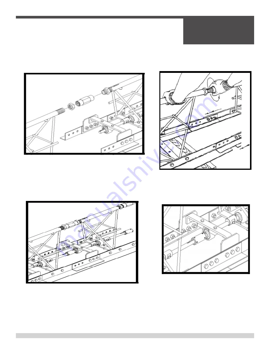
The following figures describe the proper instructions for correctly assembling engine driven screed. Make sure 

you follow the instructions in order. If the assembling of your screed is not done in this order, there could be some 

problems in trying to maintain floor flatness because your screed is not level. Levelness of your screed is critical!

STEP 1: 

Screw jam nuts onto top pipe. Start the top pipe coupler 

onto the top pipe of the mating truss section. Only thread the 
coupler on about three turns

NOTE: 

The right and left hand jam nuts will already be installed 

on the screed section.
TIGHTEN JAM NUTS AFTER SCREED IS LEVEL

STEP 2:

 Slide screed sections together until top 

pipe threads on screed marked “R” line up with 
threads in coupler on the screed. Start coupler 
on adjoining threads by hand to prevent cross 
threading.

STEP 3:

 Bearing support bolts should be loose so that 

splice plate can move in clearance holes. With 15” adjust-

able wrench, turn top pipe coupler until screed an bull float 

blades contact, then back the coupler off slightly so that the 
blades touch without tension.

STEP 4: 

Tighten bolts on splice plates. Next slide 

the shaft coupler on the adjoining section and 
tighten the set screws provided. make sure that 
the 3/16 key is on the shaft before sliding sec-
tions together. Repeat these steps for attaching all 
engine driven screed sections.

Section Assembly

Содержание SE12

Страница 1: ...OPERATIONS PARTS MANUAL Manual Part 064633 Revision C Language English Original Instructions T R U S S S C R E E D SE12 ...

Страница 2: ...This manual or a copy of it must be kept with the machine at all times There is a manual storage container located on the machine for your convenience ...

Страница 3: ...ion 022380 Screed Truss Steel Engine Driven SE12 2 Section 61M 027986 Screed Truss Steel Engine Driven SE12 2 5 Section 76m 022379 Screed Truss Steel Engine Driven SE12 5 Section 1 5m 022378 Screed Truss Steel Engine Driven SE12 7 5 Section 2 3m 028379 Screed Truss Steel Engine Driven SE12 10 0 Section 3 1m ...

Страница 4: ... Section 1 Safety 1 1 State Regulations 18 1 2 Federal Regulations 19 1 3 Safety Information 20 1 4 Safety Symbols 21 1 5 General Safety 22 1 6 Sound Vibration Analysis 29 Section 2 Operations 2 1 Pre Operating Instructions 32 2 2 Operating Instructions 33 2 3 Lifting Procedures 34 2 4 Section Assembly 35 2 5 Attaching Winches 36 2 6 Determining Left and Right 37 2 7 End Handle Assembly 38 2 8 Eng...

Страница 5: ... 4 5 Section 54 4 5 7 1 2 Section 56 4 6 10 Section 58 4 7 End Handle 60 4 8 Winch Assembly 62 4 9 Hydraulic Winch Assembly 64 4 10 Flex Coupler 68 4 11 U Joint 69 4 12 Crown Invert Bracket 70 4 13 End Mount Engine Assembly 72 4 14 Decals Standard SE12 74 4 15 Decals Hydraulic 75 Revision Details 76 Copyright Information 77 Table of Contents continued ...

Страница 6: ...t alterations or repairs made to the product without the written approval of Allen Allen specifically excludes from warranty any damage to any trowels resulting from an impact to the rotors 7 Impact damage to gear boxes is not covered under the Allen warranty and is deemed customer abuse 8 Allen will pay shop labor on warranty items at the Allen Shop Labor Rate in existence on the date of the warr...

Страница 7: ... into the following sections Complete any warranty requirements as specified by the engine manufacturer in their instructions found inside the manual box located on the back of the riding trowel operator s seat Your engine and clutch is not manufactured by Allen Engineering Corporation Inc and therefore is not covered under Allen Engineering Corporation Inc warranty Your engine manufacturer should...

Страница 8: ...____Mobile Phone _____________________ Additional Comments ______________________________________________________ ________________________________________________________________________ ________________________________________________________________________ Your Dealer has Allen Engineering Corporation trained mechanics and original Allen replacement parts Always contact the Allen Dealer who sol...

Страница 9: ...able 2 Include correct description and part number from the PARTS section of this manual 3 Specify exact shipping instructions including the preferred routing and complete destination address 4 DO NOT return parts to AEC without receiving written authorization from AEC All authorized returns must be shipped pre paid 5 When placing an order please contact the AEC dealer nearest you ALL INFORMATION ...

Страница 10: ...haracter or group of characters of the Model Number and Serial Number codes Model Number T150 B Series B Triple Roller Tube Paver 150 Serial Number The serial number found on the identification plate is a ten digit format The model number identifies your machine and will ensure that you receive the correct replacement parts Serial Number Example T15 14 01 180 Series Sequence Number Year Month Mode...

Страница 11: ...any time Please record the information found on this plate below so it will be available should the identification plate become lost or damaged When ordering parts or requesting service information you will ALWAYS be asked to specify the model and serial numbers of the machine FILL IN FOR FUTURE REFERENCE Model Number ____________________________ Serial Number ____________________________ Date Pur...

Страница 12: ...rofile Kit 115 52 075815 9 5 HP Engine Kohler Kit 122 55 028327 11 HP Engine Honda Low Profile Kit 118 54 543000 Truss screed dolly standard 45 20 543001 Truss screed dolly heavy duty 87 39 Top Pipe Coupling System Fine Thread Adjustment 1 5 16 16tpi with Full Flow 1 Non Restricting Air System with Dual Locking Jam Nuts Vibration Proff Welds with Exclusive Vibration Dampening System Bolt On Blades...

Страница 13: ... Centrifugal Fly weight Type Cooling System Forced Air Forced Air Starting Method Recoil Start Recoil Start Spark Plug Type BPR6ES NGK BPR6ES NGK Spark Plug Gap 0 028 0 031 in 0 70 0 80 mm 0 028 0 031 in 0 70 0 80 mm Dimension L x Wx H 15 0 x 16 8 X 16 6 in 381 X 428 X 422 mm 15 9 x 18 1 X 17 6 in 406 X 460 X 448 mm Dry Net Weight 55 1 lbs 25 Kg 69 8 lbs 31 7 Kg Engine Specifications MODEL Kohler ...

Страница 14: ... will not slip Utilize a spreader bar of proper length and lifting capacity Secure lifting straps from both ends of the spreader bar to the attached lifting brackets Connect lifting cables from the spreader bar to the lifting hook of a crane or forklift Ensure that the lifting hook and chain are of appropriate lifting capacity Use crane or forklift to hoist screed onto a flatbed truck for transpor...

Страница 15: ...he screed on a flatbed truck or a trailer during transportation as shown below Attach suitable tie down straps to the screed to secure it Route tie down straps over truss frame sections as required STRAP STRAP Transportation ...

Страница 16: ...s manual are illustrated on this page the geight and width are in Figure 1 and the lengths of the different screed sections available are illustrated in Figure 2 FIGURE 1 FIGURE 2 90 2 SECTION 2 1 2 SECTION 5 SECTION 7 1 2 SECTION 10 SECTION 21 187 57 187 87 187 116 650 Standard Machine Dimensions ...

Страница 17: ...SECTION 1 SAFETY 064633 Page 17 SECTION 1 SAFETY ...

Страница 18: ...SECTION 1 SAFETY 064633 Page 18 State Regulations Proposition 65 Warning ...

Страница 19: ...SECTION 1 SAFETY 064633 Page 19 Federal Regulation Respiratory Hazard ...

Страница 20: ...inform you about potential hazards that could injure you or others The safety notes specifically address the level of exposure to the operator and are preceded by one of four words DANGER WARNING CAU TION or NOTICE Indicates a hazardous situation which if not avoided will result in death or serious injury Indicates a hazardous situation which if not avoided could result in death or serious injury ...

Страница 21: ...AFETY 064633 Page 21 Potential hazards associated with the operation of this equipment will be referenced with hazard symbols which may appear throughout this manual in conjunction with safety notes Safety Symbols ...

Страница 22: ...ile the equipment is in operation ALWAYS wear adequate hearing protection while running your air powered screed DO NOT use the equipment for any purpose other than its intended purposes or applications This equipment should only be operated by trained and qualified personnel 18 years of age and older Whenever necessary replace serial plate operation and safety decals when they become difficult to ...

Страница 23: ...nt or engine NEVER operate the equipment in an explosive atmosphere or near combustible materials An explosion or fire could result causing severe bodily harm or even death If applicable never use your hand to find hydraulic leaks Use a piece of wood or cardboard Hydraulic fluid injected into the skin must be treated by a knowledgeable physician immediately or severe injury or death can occur ALWA...

Страница 24: ...s or guards removed Keep fingers hands hair and clothing away from all moving parts to prevent injury ALWAYS disconnect spark plugs before servicing engine to prevent accidental start up DO NOT remove the engine oil drain plug while the engine is hot The possibility of hot oil exists which could cause severe scalding NEVER touch the hot exhaust manifold muffler or cylinder Allow these parts to coo...

Страница 25: ... appropriate containers in well ventilated areas and away from sparks and flames NEVER use fuel as a cleaning agent DO NOT smoke around or near the equipment Fire or explosion could result from fuel vapors or if fuel is spilled on a hot engine TRANSPORTATION SAFETY NEVER allow any person or animal to stand underneath the equipment while lifting NEVER lift or transport screed with personnel standin...

Страница 26: ...during transport by securing the equipment with rope TOWING SAFETY Check with your local county or state safety towing regulations in addition to meeting Department of Transportation DOT Safety Towing Regulations before towing your screed In order to reduce the possibility of an accident while transporting the screed on public roads ALWAYS make sure the trailer that supports the screed and the tow...

Страница 27: ...kidding or jack knifing Smooth gradual starts and stops will im prove towing Avoid sharp turns to prevent rolling Trailer should be adjusted to a level position at all times when towing Raise and lock trailer wheel stand in up position when towing Place chock blocks underneath wheel to prevent rolling while parked Place support blocks underneath the trailer s bumper to prevent tipping while parked...

Страница 28: ...g to modify or make adjustments to the engine emission system by unauthorized personnel without proper training could damage the equipment or create an unsafe condition Additionally modifying the fuel system may adversely affect evaporative emissions resulting in fines or other penalties ENVIRONMENTAL SAFETY Decommissioning is a controlled process used to safely retire a piece of equipment that is...

Страница 29: ...ion above was acquired through vibration and sound analysis taken here at AEC A certified sound and vibration technician was hired to test several of our products All of the data collected was measured according to OSHA standards ISO 3744 If there are any questions on this particular subject contact AEC Customer Service at 870 236 7751 o4 800 643 0095 Sound Vibration Analysis ...

Страница 30: ...SECTION 1 SAFETY 064633 Page 30 Notes ...

Страница 31: ...SECTION 2 OPERATIONS 064633 Page 31 SECTION 2 OPERATIONS ...

Страница 32: ...aulic winches if applicable Check winch cables to make sure that they will not loosen during the screed run Look over the forms to check for unevenness so that the screed will not hang up Ask yourselves these questions when preparing your screed for a job What is the exact pour width What is the slump Is the slab flat crowned or inverted What is the required surface tolerance Choose screed type an...

Страница 33: ...creed Consider the use of HD winches 6 extension handles What do you do when you are up against a wall a wall bracket b pipe rail c form CONCRETE Are there any mix characteristics or additives that effect the performance of the screed Will the supply of concreete be steady or intermittent Be aware of the importance of WEATHER THE CREW Two key people should be trained to operate the scree The scree...

Страница 34: ...he only source of lift the screed It is quite obvious that two large men will not be able to lift 70 feet of screed the following list of maximum screed lengths is very important so that the length of your screed will not be too long SX SCREED MAXIMUM 60 FEET HD SCREED MAXIMUM 60 FEET SHD SCREED MAXIMUM 60 FEET For proper lifting of an average screed 30 ft the screed lifting hook is an ideal item ...

Страница 35: ...he screed section TIGHTEN JAM NUTS AFTER SCREED IS LEVEL STEP 2 Slide screed sections together until top pipe threads on screed marked R line up with threads in coupler on the screed Start coupler on adjoining threads by hand to prevent cross threading STEP 3 Bearing support bolts should be loose so that splice plate can move in clearance holes With 15 adjust able wrench turn top pipe coupler unti...

Страница 36: ...he cables are not attached properly the cables could snap loose causing severe injury to finishing personnel surrounding the screed To attach the winch cables properly adhere to the following instructions Take the cable and go around the last form stake Make sure that you go underneath the form Attach the cable hook to the next form stake from the end Attaching Winches to Form Stakes ...

Страница 37: ...erial number this is probably the easiest way to determine the left and right sides of the screed assembly The right side has the model number and the 5 digit serial number The left hand side is only stamped with an L Also the from of the screed is determined by the two screed blades mounted back to back The rear of the screed has only one bull float blade Determining Left and Right of Screed Sect...

Страница 38: ...o your screed Mount the bearing onto the bearing support bracket Mount the handle grips onto the lifting handles Mount the lifting handles onto the end handle using two 3 8 x 2 bolts and 3 8 nylon lock nuts Mount the bearing support bracket to the end handle using four 1 4 x 1 1 2 bolts and 1 4 stover nuts Mount the end handle to the screed using three 1 2 x 3 4 bolts three 1 2 x 1 bolts and six 1...

Страница 39: ...y to the drive shaft 1 Start by attaching the rubber bushing to the top bar of the screed Proceed to place the clamp and clamp spacer around the bushing Tighten the engine mount onto the screed with the 4 3 8 16 x 3 3 4 hex screws 3 8 washer and 3 8 hex nut 2 Line the engine up with the holes shown in the figure at 2 1 Tighten the 1 2 13 x 1 hex screw 1 2 washer and 1 2 13 hex nut to the screed 2 ...

Страница 40: ...de of the wooden support Stretch a line as tight as possible from nail to nail Make sure that the nail is contacting each support at the pint of blade contact NOTE The supports do not have to be on the same level Use a short flat piece of metal or wood as a gauge block to compare the string to the bot tom surface of the screed blade and bull float blade The blades should be equal to each other at ...

Страница 41: ...SECTION 3 SERVICE 064633 Page 41 SECTION 3 SERVICE ...

Страница 42: ...EC tool part number 020255 When connecting drive shafts assemble with all the weights on each section facing the bull float blade if weights are mis matched the screed will no vibrate properly Match the key ways on the drive shafts and the connectors Do not over speed engine RPM must not exceed 3600 RPM Shaft speed will not exceed design limits if engine speed maximum is adhered to DO NOT crown or...

Страница 43: ... additional information on engine maintenance A copy of the engine operator s manual was supplied with the machine when it was shipped TABLE CHECK LIST ITEM DAILY EVERY 20 HRS EVERY 50 HRS EVERY 100 HRS EVERY 300 HRS Check engine oil level ü Check tighten external hardware ü Check drive belt for wear ü Check valve clearance ü Change engine oil ü Replace engine oil filter ü Replace spark plug ü ...

Страница 44: ...lectronic components Examples include electronic displays lights switches wiring etc The electronic components may be damaged if water is sprayed on them Keep a perpendicular angle 90 when cleaning over a decal Holding nozzle of a pressure washer at an angle different from 90 may lift the decal from the machine Recommended using a safe cement dissolver BACK SET or similar to remove hardened concre...

Страница 45: ...SECTION 4 PARTS 064633 Page 45 SECTION 4 Parts ...

Страница 46: ... accurate delivery All set screws have blue LOC TITE applied at the factory If set screw is removed or loosened for any reason re apply blue LOC TITE All grease fittings are capped with CAP PLUG GC 5 AEC PN 015692 to protect the fitting If cap becomes missing or damaged replace it as soon as possible Anti Seize is applied at the factory to drive line couplings and moving components If these parts ...

Страница 47: ...riate part number not the key number This manual contains an illustrated parts list for help in ordering replacement parts for your machine Follow the instructions below when ordering parts to insure prompt and accurate delivery 1 All orders for service parts include the serial number for the machine Shipment will be delayed if this information is not available 2 Include correct description and pa...

Страница 48: ...SECTION 4 PARTS 064633 Page 48 U M Y 2 28 1 7 21 14 26 10 9 18 25 24 23 38 3 19 13 4 6 11 20 6 3 17 9 10 2 16 4 1 Engine Mount Illustration ...

Страница 49: ... 012894 DECAL CAUTION KEEP HANDS AWAY SHAFT 1 15 012974 FASTENER HHCS 5 16 24 X 3 4 4 16 016191 DECAL ALLOW ENG TO COOL 1 17 017751 FASTENER FLAT WASHER HARD A325 3 8 p 12 18 020698 PULLEY 2BK30X3 4 2 SET SCREWS p 9HP 1 022549 PULLEY 2BK36 X 3 4 MODIFIED p 11HP 1 19 027871 BRACKET ANGLE 5 8 11 HP LOPRO 1 20 027872 T MOUNT ENGINE 8 11 HP LOPRO 1 21 027877 GUARD BELT 8 11 HP LOPRO 1 22 027878 BRACKE...

Страница 50: ...SECTION 4 PARTS 064633 Page 50 U M 20 10 7 19 19 19 19 19 8 8 10 9 4 6 24 25 11 22 1 27 11 12 17 14 13 18 21 15 5 2 4 2 2 Foot Section Illustration ...

Страница 51: ...X 1 1 2 GR 8 4 13 017751 FASTENER FLAT WASHER HARD A325 3 8 p 4 14 020514 FASTENER NUT STOVER LOCK 3 8 16 4 15 020716 DRIVE SHAFT 1 16 029270 ECCENTRIC WEIGHT HD AGC SCD 2 17 010005 FASTENER HHCS 1 4 20 X 1 1 2 GR 8 2 18 020542 FASTENER NUT STOVER LOCK 1 4 20 2 19 010067 FASTENER HHCS 1 2 13 X 1 GR8 11 20 010068 FASTENER HHCS 1 2 13 X 1 1 4 GR 5 3 21 010273 KEY 3 16 SQ X 2 2 22 020635 COUPLER SHAF...

Страница 52: ...ON 4 PARTS 064633 Page 52 U M QTY 1 1 6 16 2 1 1 2 1 2 2 4 4 4 1 2 2 2 11 3 2 1 2 2 2 2 2 1 20 10 7 19 19 19 19 19 8 8 10 9 4 6 24 25 11 22 1 27 11 12 17 14 13 18 21 15 5 2 4 3 2 5 Foot Section Illustration ...

Страница 53: ...2 12 028402 FASTENER HHCS 3 8 16 X 1 1 2 GR 8 4 13 017751 FASTENER FLAT WASHER HARD A325 3 8 p 4 14 020514 FASTENER NUT STOVER LOCK 3 8 16 4 15 020716 DRIVE SHAFT 1 16 029270 ECCENTRIC WEIGHT HD AGC SCD 2 17 010005 FASTENER HHCS 1 4 20 X 1 1 2 GR 8 2 18 020542 FASTENER NUT STOVER LOCK 1 4 20 2 19 010067 FASTENER HHCS 1 2 13 X 1 GR8 11 20 010068 FASTENER HHCS 1 2 13 X 1 1 4 GR 5 3 21 010273 KEY 3 1...

Страница 54: ...ECTION 4 PARTS 064633 Page 54 U M TY 4 12 12 28 3 1 2 1 6 1 6 1 6 1 1 1 3 1 3 2 1 2 3 30 4 3 2 2 2 3 23 23 25 25 24 25 28 12 8 26 7 17 10 6 21 20 15 14 19 22 13 12 12 9 11 4 4 5 Foot Section Illustration ...

Страница 55: ...2 022190 SHAFT ASS Y 5 STD HED 1 13 028402 FASTENER HHCS 3 8 16 X 1 1 2 GR 8 6 14 036669 DECAL HEARING PROTECTION 1 1 15 037501 DECAL MODEL 12 HED 1 16 038400 COUPLER STEEL SCREED LH TOP PIPE 1 17 044834 ASSEMBLY STEEL TOP PIPE COUPLER 1 18 039351 TIE 15 0 LG BLK STD CABLE Ø3 000 1 19 039893 DECAL CE 1 20 049413 DECAL RAZORBACK TRUSS SCREED 1 21 053446 DECAL MADE IN USA SP 1 22 056336 DECAL AEC 1 ...

Страница 56: ...SECTION 4 PARTS 064633 Page 56 19 13 13 15 10 15 10 14 14 15 10 9 14 14 3 3 4 11 10 12 2 2 1 31 17 22 25 27 23 29 26 24 28 6 7 4 5 7 5 Foot Section Illustration ...

Страница 57: ...7 FASTENER HHCS 1 2 13 X 1 GR8 9 14 010068 FASTENER HHCS 1 2 13 X 1 1 4 GR 5 15 15 010066 FASTENER HHCS 1 2 13 X 3 4 GR 5 16 16 012401 PLUG 1 4 NPT M P 28 PLASTIC 5 17 108000 JAM NUT RH SX ED 1 18 108001 JAM NUT LH SX ED 1 19 038401 COUPLER STEEL SCREED RH TOP PIPE 1 20 038400 COUPLER STEEL SCREED LH TOP PIPE 1 21 010036 FASTENER HHCS 3 8 16 X 1 2 22 012894 DECAL CAUTION KEEP HANDS AWAY SHAFT 1 23...

Страница 58: ...SECTION 4 PARTS 064633 Page 58 U M Y 25 9 34 12 23 28 30 24 29 31 8 38 23 28 30 24 31 8 3 2 37 4 3 5 16 20 19 10 6 17 32 22 21 32 6 1 35 18 13 36 11 18 4 6 10 Foot Section Illustration ...

Страница 59: ... 4 20 8 16 020635 COUPLER SHAFT 2 17 020704 BEARING 3 4 PB p 6 18 028402 FASTENER HHCS 3 8 16 X 1 1 2 GR 8 12 19 029270 ECCENTRIC WEIGHT HD AGC SCD 8 20 032112 SHAFT DRIVE ED SCREED 5 10 KW 2 21 032138 BLADE SCREED HED 2 22 032139 BLADE BULL FLOAT HED 1 23 036669 DECAL HEARING PROTECTION 1 2 24 037501 DECAL MODEL 12 HED 2 25 044834 ASSEMBLY STEEL TOP PIPE COUPLER 3 26 038401 COUPLER STEEL SCREED R...

Страница 60: ...ARTS 064633 Page 60 U M QTY 1 1 2 1 1 1 2 1 1 2 1 1 1 1 1 1 1 1 1 4 2 1 1 1 1 3 2 2 8 1 1 1 1 7 6 1 1 1 1 1 21 27 13 28 14 16 60 21 79 30 84 29 26 52 41 1 15 12 80 74 76 63 20 4 7 End Handle Assembly Illustration ...

Страница 61: ...ULLEY BLOCK HD W EYEBOLT p 1 41 038280 ASSEMBLY HYD WINCH REEL 1 52 110102 WINCH HANDLE 1 60 010005 FASTENER HHCS 1 4 20 X 1 1 2 GR 8 6 63 010007 FASTENER HHCS 1 4 20 X 2 4 70 106001 PLATE SPLICE 10GA 2 71 010067 FASTENER HHCS 1 2 13 X 1 GR8 5 72 010106 FASTENER NUT HEX 1 2 13 GR8 15 73 010068 FASTENER HHCS 1 2 13 X 1 1 4 GR 5 10 74 010039 FASTENER HHCS 3 8 16 X 1 3 4 LONG GR8 1 75 010091 FASTENER...

Страница 62: ...SECTION 4 PARTS 064633 Page 62 U M QTY 1 2 2 1 2 1 1 1 1 1 1 1 1 1 1 1 1 1 1 1 1 1 19 19 19 18 19 12 7 15 13 23 2 5 1 16 4 3 21 16 14 11 8 9 10 4 20 6 6 6 17 22 4 8 Winch Assembly Illustration ...

Страница 63: ...07255 ROLL PIN 1 9 404878 SPACER SLEEVE 1 10 404872 SHORT SLEEVE 1 11 404868 REVERSIBLE SLEEVE 1 12 404889 BRAKE LEVER 1 13 404909 BRAKE PIN 1 14 205135 E RING 1 15 404908 BRAKE BAND 1 16 304294 HANDLE ASSEMBLY 1 17 204804 CAP SCREW 1 18 204808 REEL SPACER 1 19 304728 REEL ASSEMBLY 1 20 204803 LOCK NUT 1 21 404180 HANDLE SPRING 1 22 205006 DRIVE SHAFT 0 25 1 23 205014 LOCK NUT 1 4 8 Winch Assembly...

Страница 64: ...ION 4 PARTS 064633 Page 64 58 31 40 61 62 20 63 1 22 68 24 23 67 65 38 38 65 83 44 47 59 46 45 57 36 39 43 82 85 32 41 78 50 61 42 74 81 41 37 77 75 80 52 30 79 84 4 9 Hydraulic Winch Assembly Illustration ...

Страница 65: ...1 038280 ASSEMBLY HYD WINCH REEL 1 42 034011 MOTOR WHITE 255320F3710AAAAA 1 43 029107 VALVE FLOW CONTROL MCD 5439 1 44 034012 1 X 1 2 TANK SUCTION STRAINER W O BTPASS TMF 05 0 1 45 023838 CNTCTR 9 16X1 4 STRTTHD ORING p 3 46 027925 FTG FL NIPPLE 3 8 X 1 4 37 DG 1 47 023414 ELBOW 1 2 X1 2 90DEG 1 50 029109 ROD SPRING 1 51 029270 ECCENTRIC WEIGHT HD AGC SCD 2 52 110102 HANDLE 1 57 029398 HOSE ASSEMB...

Страница 66: ... 5 16 18 X 1 1 4 GR5 4 68 010273 KEY 3 16 SQ X 2 2 74 010039 FASTENER HHCS 3 8 16 X 1 3 4 LONG GR8 1 75 010091 FASTENER LOCK WASHER 3 8 6 76 010102 FASTENER NUT HEX 3 8 16 1 77 010036 FASTENER HHCS 3 8 16 X 1 4 78 010003 FASTENER HHCS 1 4 20 X 1 2 79 110008 HOOK SLIP 1 4 PLATED BULK 1 80 000751 CABLE 5 32 7 X 19 GALV 1 81 022297 FASTENER SQHSS 5 16 24 X 1 3 82 SHCS SHCS VALVE 4 83 010019 FASTENER ...

Страница 67: ... NWO 6 8 027925 FITTING FL NIPPLE 3 8 X 1 4 2404 4 6 2 9 023414 FITTING ELBOW 90 1 2 X 1 2 2501 8 8 2 10 045921 FITTING STRAIGHT 6400 8 8 O 2 11 035564 PLUG 1 4 HEX HOLLOW PIPE 5406 HHP 4 2 12 029400 HOSE LEFT HAND ASSEMBLY 16 1 2 DIAMETER 29400 SKD 1 13 029401 HOSE RIGHT HAND ASSEMBLY 16 1 2 DIAMETER 29401 SKD 1 14 029397 HOSE ASSEMBLY 16 1 4 DIAMETER 29397 SKD 2 15 029398 HOSE ASSEMBLY 19 1 2 1 ...

Страница 68: ...Y 1 020704 BEARING 3 4 PB p 2 2 221155 SUPPORT OFF INTERMEDIAT BRG 2 3 010273 KEY 3 16 SQ X 2 2 4 017751 FASTENER FLAT WASHER HARD A325 3 8 p 6 5 020514 FASTENER NUT STOVER LOCK 3 8 16 p 4 6 010038 FASTENER HHCS 3 8 16 X 1 1 2 GR 5 4 7 020699 COUPLER FLEX 43 PG SF 2 7 8 1 8 022599 COUPLER LRG T P BALL JOINT 1 5 16 p 1 4 10 Flex Coupler Assembly Illustration Parts List ...

Страница 69: ... 020514 FASTENER NUT STOVER LOCK 3 8 16 4 2 221155 SUPPORT OFF INTERMEDIAT BRG 2 3 010273 KEY 3 16 SQ X 2 2 4 022635 UNIVERSAL JOINT ASSEMBLY MOD ED SC p 1 5 020704 BEARING 3 4 PB p 2 6 010038 FASTENER HHCS 3 8 16 X 1 1 2 GR 5 4 7 017751 FASTENER FLAT WASHER HARD A325 3 8 p 6 4 11 U Joint Assembly Illustration Parts List ...

Страница 70: ...SECTION 4 PARTS 064633 Page 70 21 1 32 14 13 20 30 28 19 11 2 3 4 12 15 17 7 16 8 22 26 10 31 29 5 6 27 9 27 26 4 12 Crown Invert Bracket Assembly Illustration ...

Страница 71: ...E 12HD LH CROWN INVERT SCD p 2 13 010440 ROD RH CROWN ADJ 1 14 010441 ROD LH CROWN ADJ 1 15 010454 ROD RH INVERT ADJ 2 16 010455 ROD RH INVERT ADJ 2 17 016885 TURNBUCKLE INVERT COUPLER ASSEMBLY 2 18 017751 FASTENER FLAT WASHER HARD A325 3 8 p 8 19 018212 HANDLE CROWN INVERT 2 20 020514 FASTENER NUT STOVER LOCK 3 8 16 4 21 020704_A BEARING 3 4 PB p 2 22 022635 UNIVERSAL JOINT ASSEMBLY MOD ED SC p 1...

Страница 72: ...SECTION 4 PARTS 064633 Page 72 4 13 End Mount Engine Assembly Illustration ...

Страница 73: ... ENGINE MOUNT 1 16 102003 BLADE SCREED 18 2 17 104003 BLADE BULLFLOAT 18 1 18 010066 BOLT 1 2 X 3 4 6 19 010067 BOLT 1 2 X 1 6 20 010106 NUT HEX 1 2 12 21 010273 KEY 1 22 020720 V BELT 2 23 020698 PULLY 1 24 010023 BOLT 5 16 X 1 3 4 4 25 010040 BOLT 3 8 X 2 2 26 010464 NUT NYLON 2 27 017066 HANDLE 2 28 015767 GRIP HANDLE 2 29 124000 THROTTLE ASSEMBLY 1 30 010002 BOLT 1 4 X 3 4 2 31 020542 NUT STOV...

Страница 74: ...d SE12 Screed Razorback Decal Part 068418 Model Decal Part 068419 CE Decal Part 068414 Pinch Decal 0 75 X 0 75 Part 068406 Crown Decal Part 068417 Belt Warning Decal Part 068416 Model Decal Part 068413 Engine Warning Decal Part 068415 Allen Decal Part 068420 ...

Страница 75: ... 4 15 Decals 068421 Hydraulic SE12 Screed Hyd Fill Decal Part 068424 Pinch Decal 1 25 X 1 25 Part 068422 Cables Decal Part 068423 HYDRAULIC SCREED DECAL KIT 068421 INCLUDE DECALS LOCATED ON PREVIOUS PAGE PLUS THE THREE INCLUDED HERE ...

Страница 76: ... PARTS 064633 Page 76 Revision Detail MANUAL REVISION DETAIL REVISION REVISION DATE REVISION REFERENCE REVISION BY 10 15 Initial Release AW A 06 16 AW B 06 18 MN 18 011 18 020 18 060 MW C 01 22 Updated Covers MK ...

Страница 77: ...ny errors or inaccuracies that may appear in this manual Allen Products are covered under one or more of the following patent numbers U S Design Patents 344 736 400 542 400 544 402 998 402 999 403 332 404 041 404 042 410 931 413 127 416 564 465 897 466 909 474 203 U S Utility Patents 5 108 220 5 238 323 5 328 295 5 352 063 5 405 216 5 476 342 5 480 257 5 480 258 5 533 831 5 562 361 5 567 075 5 613...

Страница 78: ...E T P A R A G O U L D A R K A N S A S 7 2 4 5 0 8 7 0 2 3 6 7 7 5 1 8 0 0 6 4 3 0 0 9 5 T O L L F R E E U S A O N LY MAILING P O B O X 8 1 9 P A R A G O U L D A R K A N S A S 7 2 4 5 1 A L L E N E N G C O M C O N N E C T W I T H U S O N S O C I A L ...

Отзывы: