158
Rockwell Automation Publication 825-UM004D-EN-P - November 2012
Chapter 11
Testing & Troubleshooting
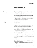
Field Serviceability
The 825-P firmware can be upgraded in the field (refer to
for
firmware upgrade instructions). By monitoring the front-panel messages, the user
will be aware of a self-test failure occurrence. By using the metering functions, the
user will be aware if the analog front-end (not monitored by relay self-test) is
functional.
The only two components that can be replaced in the field are (1) the power
supply fuse and (2) the real-time clock (RTC) battery.
Power Supply Fuse Replacement
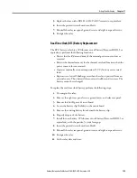
To replace the power supply fuse, perform the following steps:
1.
De-energize the relay.
2.
Remove the eight rear panel screws, ground screw, and relay rear panel.
3.
Remove the Slot A printed circuit board.
4.
Locate the fuse on the board, then remove the fuse from the fuse holder.
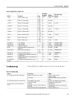
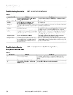
The relay does not respond to commands from a device
connected to the serial port.
Cable is not connected.
Verify the cable connections.
Cable is not the correct type.
Verify the cable pinout.
The relay or device is at an incorrect baud rate or has
another parameter mismatch.
Verify Device software setup.
The relay serial port has received an XOFF, halting
communications.
Type
<Ctrl> Q
to send the relay XON and restart
communications.
The relay does not respond to faults.
The relay is improperly set.
Verify the relay settings.
Improper test source settings.
Verify the test source settings.
Current or voltage input wiring error.
Verify input wiring.
Failed relay self-test.
Use the front panel
RELAY STATUS
function to view self-
test results.
The relay trips on overload sooner than expected.
The phase rotation is improperly set.
Verify phase rotation setting as described in
or
The FLA is improperly set.
Verify FLA settings.
The SF is improperly set.
Verify the Service Factor of the motor.
Table 90 - Troubleshooting
Problem
Possible Cause
Solution
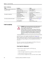
ATTENTION:
Disconnect or de-energize all external connections before opening this
device. Contact with hazardous voltages and currents inside this device can cause
electrical shock that can lead to injury or death.
Equipment components are sensitive to electrostatic discharge (ESD). Undetectable
permanent damage can result if you do not use proper ESD procedures. Ground yourself,
your work surface, and this equipment, before removing any cover from this equipment.
If your facility is not equipped to work with these components, contact Rockwell
Automation about returning this device and related Rockwell Automation equipment
for service.
Содержание 825-P
Страница 1: ...Modular Protection System for Motors Catalog Number 825 P User Manual...
Страница 4: ...4 Rockwell Automation Publication 825 UM004D EN P November...
Страница 44: ...44 Rockwell Automation Publication825 UM004D EN P November 2012 Chapter 3 Front Panel Operation...
Страница 64: ...64 Rockwell Automation Publication825 UM004D EN P November 2012 Chapter 5 Using MPS Explorer...
Страница 104: ...104 Rockwell Automation Publication825 UM004D EN P November 2012 Chapter 6 Configuring Protection Logic Functions...
Страница 130: ...130 Rockwell Automation Publication825 UM004D EN P November 2012 Chapter 9 825 PDN DeviceNet Communication Card...
Страница 182: ...182 Rockwell Automation Publication825 UM004D EN P November 2012 Chapter 12 ASCII Serial Communications...
Страница 186: ...186 Rockwell Automation Publication825 UM004D EN P November 2012 Chapter 13 Firmware Upgrade Instructions...
Страница 234: ...234 Rockwell Automation Publication 825 UM004D EN P April 2012 Chapter B ParameterList...
Страница 265: ......

