background image

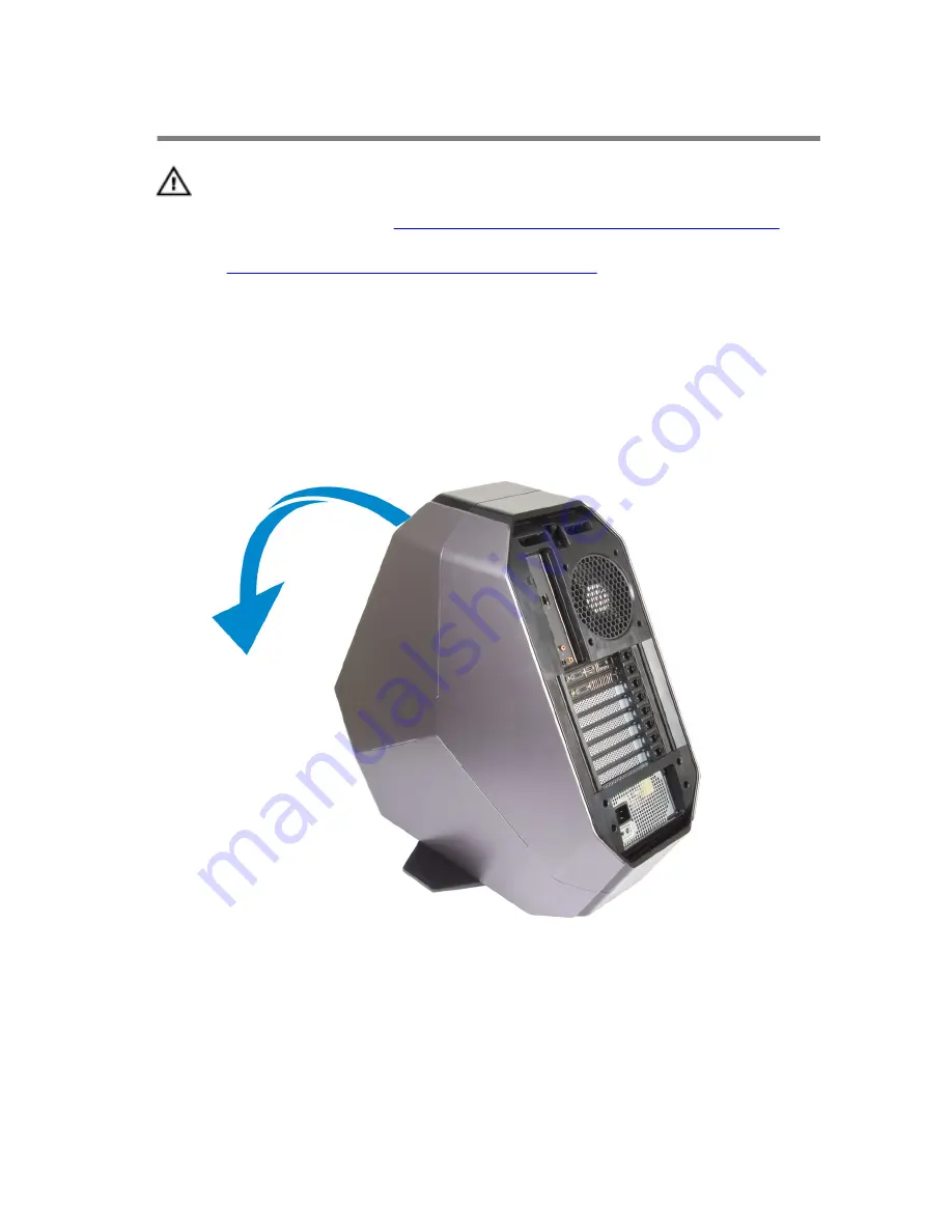
Removing the Stability Foot

WARNING: Before working inside your computer, read the 

safety information that shipped with your computer and 

follow the steps in 

Before Working Inside Your Computer

After working inside your computer, follow the instructions 

in 

After Working Inside Your Computer

. For more safety best 

practices, see the Regulatory Compliance home page at 

dell.com/regulatory_compliance. 


Procedure

Tilt the computer towards the front until the base is facing up.

Remove the screws that secure the stability foot to the computer.

22

Содержание Area-51 R2

Страница 1: ...Alienware Area 51 Service Manual Computer Model Alienware Area 51 R2 Regulatory Model D03X Regulatory Type D03X001...

Страница 2: ...roblem WARNING A WARNING indicates a potential for property damage personal injury or death Copyright 2014 Dell Inc All rights reserved This product is protected by U S and international copyright and...

Страница 3: ...r 13 Technical Overview 14 Inside View of Your Computer 14 Right View 15 Left View 16 System Board Components 17 I O Board Components 18 Lifting the Computer 20 Procedure 20 Removing the Stability Foo...

Страница 4: ...33 Prerequisites 33 Procedure 33 Replacing the Battery Case 36 Procedure 36 Post requisites 36 Removing the Hard Drive 37 Prerequisites 37 Procedure 37 Replacing the Hard Drive 40 Procedure 40 Post r...

Страница 5: ...isites 48 Removing the Left AlienFX Side Panel Connector 49 Prerequisites 49 Procedure 49 Replacing the Left AlienFX Side Panel Connector 53 Procedure 53 Post requisites 53 Removing the I O Board 54 P...

Страница 6: ...ocedure 64 Post requisites 65 Removing the Graphics Card 66 Prerequisites 66 Procedure 66 Replacing the Graphics Card 69 Procedure 69 Post requisites 69 Removing the Multiple Graphics Cards 70 Prerequ...

Страница 7: ...dure 85 Post requisites 85 Removing the Front bezel Heat sensor 86 Prerequisites 86 Procedure 86 Replacing the Front bezel Heat sensor 88 Procedure 88 Post requisites 88 Removing the Memory Fan 89 Pre...

Страница 8: ...dure 99 Post requisites 100 Removing the Power Supply Unit 101 Prerequisites 101 Procedure 101 Replacing the Power Supply Unit 104 Procedure 105 Post requisites 106 Removing the Coin Cell Battery 107...

Страница 9: ...Logo Board 116 Procedure 116 Post requisites 116 Removing the System Board 117 Prerequisites 117 Procedure 118 Replacing the System Board 119 Procedure 119 Post requisites 119 System Setup 121 Overvi...

Страница 10: ...erent operating system see the documentation of your operating system for shut down instructions 3 Disconnect your computer and all attached devices from their electrical outlets 4 Disconnect all cabl...

Страница 11: ...fety instructions for complete information about safety precautions working inside your computer and protecting against electrostatic discharge CAUTION Before touching anything inside your computer gr...

Страница 12: ...N Press and eject any installed card from the media card reader Recommended Tools The procedures in this document may require the following tools Philips screwdriver Flat head screwdriver Plastic scri...

Страница 13: ...sure that no stray screws remain inside your computer 2 Connect any external devices peripherals and cables you removed before working on your computer 3 Replace any media cards discs and any other pa...

Страница 14: ...Working Inside Your Computer After working inside your computer follow the instructions in After Working Inside Your Computer For more safety best practices see the Regulatory Compliance home page at...

Страница 15: ...1 processor liquid cooling assembly fan 2 graphics card 3 system board 4 power supply 5 AlienFX side panel connector 6 PCI fan 7 processor liquid cooling assembly pump 8 memory modules 9 memory fan t...

Страница 16: ...ard IO BRD 3 drive bay heat sensor 4 2 5 inch drive bracket HDD4 HDD5 5 AlienFX side panel connector 6 rear I O accessibility lighting batteries 7 3 5 inch drive bracket HDD1 8 3 5 inch drive bracket...

Страница 17: ...omponents 1 processor liquid cooling assembly fan LCM_FAN1 2 audio connector AUDIO101 3 PCI Express x16 slot SLOT1 4 low pin count debug header LPC1 5 password reset jumper PASSWORD1 6 PCI Express x1...

Страница 18: ...onnector PCI_FAN1 20 SATA drive connectors 21 USB connector USB1 22 LED Power Switch PANEL1 23 USB connector USB3_MB1 24 Advanced Technology xTended ATX power connector ATX PWR1 25 processor socket CP...

Страница 19: ...ater lighting connector POGO_IN_L1 4 right theater lighting connector POGO_IN_R1 5 USB connector USB1 6 debug connector DEBUG1 7 front I O control connector FIO_PWR1 8 front I O connector USB3_FIO1 9...

Страница 20: ...Lifting the Computer Procedure 1 With both hands hold the handle on top of the computer 20...

Страница 21: ...2 Lift the computer 1 handle 2 computer 21...

Страница 22: ...Inside Your Computer After working inside your computer follow the instructions in After Working Inside Your Computer For more safety best practices see the Regulatory Compliance home page at dell co...

Страница 23: ...3 Lift the stability foot off the computer 1 stability foot 2 screws 2 3 computer 23...

Страница 24: ...4 Tilt the computer back to the upright position 24...

Страница 25: ...omputer follow the instructions in After Working Inside Your Computer For more safety best practices see the Regulatory Compliance home page at dell com regulatory_compliance Procedure 1 Tilt the comp...

Страница 26: ...instructions in After Working Inside Your Computer For more safety best practices see the Regulatory Compliance home page at dell com regulatory_compliance Procedure NOTE Make sure that you remove th...

Страница 27: ...3 Pull and lift the right side panel away from the chassis 1 screw 2 security cable slot latch 3 release panel 4 right side panel 4 Repeat the procedure from step 2 to step 3 on the left side panel 27...

Страница 28: ...Working Inside Your Computer For more safety best practices see the Regulatory Compliance home page at dell com regulatory_compliance Procedure 1 Align the tabs on the right side panel with the slots...

Страница 29: ...ollow the steps in Before Working Inside Your Computer After working inside your computer follow the instructions in After Working Inside Your Computer For more safety best practices see the Regulator...

Страница 30: ...Procedure Slide and open the battery case door and remove the batteries from the battery case 1 battery case door 2 AA batteries 2 30...

Страница 31: ...nd follow the steps in Before Working Inside Your Computer After working inside your computer follow the instructions in After Working Inside Your Computer For more safety best practices see the Regul...

Страница 32: ...1 battery case door 2 AA batteries 2 Post requisites Replace the right side panel See Replacing the Side Panels 32...

Страница 33: ...r working inside your computer follow the instructions in After Working Inside Your Computer For more safety best practices see the Regulatory Compliance home page at dell com regulatory_compliance Pr...

Страница 34: ...ttery compartment 1 battery case door 2 AA batteries 2 4 Press the releasing clips on the cable connector to disconnect the battery case cable from the chassis 5 Remove the screws that secure the batt...

Страница 35: ...6 Lift the battery case off the chassis 1 battery case cable 2 battery case connector 3 battery case 4 screws 2 35...

Страница 36: ...uter For more safety best practices see the Regulatory Compliance home page at dell com regulatory_compliance Procedure 1 Align the screw holes on the battery case with the screw holes on the chassis...

Страница 37: ...ry Compliance home page at dell com regulatory_compliance CAUTION Hard drives are fragile Exercise care when handling the hard drive CAUTION To avoid data loss do not remove the hard drive while the c...

Страница 38: ...the tab slide and remove the hard drive assembly from the chassis 1 power cable 2 data cable 3 chassis 4 screw 5 hard drive assembly 5 Remove the screws that secure the hard drive bracket to the hard...

Страница 39: ...6 Slide and remove the hard drive from the hard drive bracket NOTE Repeat step 2 to step 5 to remove any other hard drives installed in your computer 1 screws 4 2 hard drive 3 hard drive bracket 39...

Страница 40: ...fragile Exercise care when handling the hard drive Procedure 1 Align the screw holes on the hard drive bracket with the screw holes on the hard drive 2 Replace the screws that secures the hard drive t...

Страница 41: ...ons in After Working Inside Your Computer For more safety best practices see the Regulatory Compliance home page at dell com regulatory_compliance Prerequisites 1 Remove the stability foot 2 Remove bo...

Страница 42: ...Slide and lift the optical drive assembly of the chassis 1 screw 2 optical drive assembly 3 data cable and power cable 5 Remove the screws that secure the optical drive bracket to the optical drive 4...

Страница 43: ...6 Slide and remove the optical drive from the optical drive bracket 1 screws 2 2 optical drive 3 optical drive bracket 43...

Страница 44: ...l com regulatory_compliance Procedure 1 Align the screw holes on the optical drive bracket with the screw holes on the optical drive 2 Replace the screws that secures the optical drive to the optical...

Страница 45: ...Your Computer For more safety best practices see the Regulatory Compliance home page at dell com regulatory_compliance Prerequisites 1 Remove the stability foot 2 Remove both the left and right side p...

Страница 46: ...4 Remove the right AlienFX side panel connector assembly from the chassis 1 screw 2 right AlienFX side panel connector assembly 3 AlienFX side panel cable 4 AlienFX side panel connector 46...

Страница 47: ...5 Remove the screws that secure the right AlienFX side panel connector to the bracket and set it aside in a secure location 1 screws 2 2 right AlienFX side panel connector 47...

Страница 48: ...safety best practices see the Regulatory Compliance home page at dell com regulatory_compliance Procedure 1 Replace the screws that secure the right AlienFX side panel connector to the bracket 2 Repla...

Страница 49: ...g Inside Your Computer After working inside your computer follow the instructions in After Working Inside Your Computer For more safety best practices see the Regulatory Compliance home page at dell c...

Страница 50: ...o the I O board 1 AlienFX side panel connector 2 left AlienFX side panel cable 3 I O board 3 Turn the chassis over 4 Remove the AlienFX side panel cable through the routing holes 5 Remove the screw th...

Страница 51: ...6 Remove the left AlienFX side panel connector assembly from the chassis 1 screw 2 left AlienFX side panel connector assembly 51...

Страница 52: ...7 Remove the screws that secure the AlienFX side panel connector to the bracket and set it aside in a secure location 1 screw 2 left AlienFX side panel connector 52...

Страница 53: ...er For more safety best practices see the Regulatory Compliance home page at dell com regulatory_compliance Procedure 1 Replace the screws that secure the left AlienFX side panel connector to the brac...

Страница 54: ...our Computer After working inside your computer follow the instructions in After Working Inside Your Computer For more safety best practices see the Regulatory Compliance home page at dell com regulat...

Страница 55: ...s on the I O board NOTE Note the routing of all cables as you remove them so that you can reroute them correctly after you replace the I O board 1 cables 2 connector 3 I O board 3 Remove the screws th...

Страница 56: ...4 Remove the I O board out of the chassis 1 I O board 2 screws 2 56...

Страница 57: ...dure 1 Align the screw holes on the I O board to the screw holes on the chassis and place the I O board in the chassis 2 Replace the screws that secure the master I O board to the chassis 3 Route and...

Страница 58: ...ter Working Inside Your Computer For more safety best practices see the Regulatory Compliance home page at dell com regulatory_compliance Prerequisites 1 Remove the stability foot 2 Remove both the le...

Страница 59: ...nnector 2 drive bay heat sensor cable connector 3 drive bay heat sensor cable 4 Turn the chassis over 5 Remove the cable through the sensor bracket 6 Locate the drive bay heat sensor See Left View 7 P...

Страница 60: ...9 Slide the drive bay heat sensor cable out of the sensor bracket 1 release tab 2 securing clip 3 drive bay heat sensor cable 60...

Страница 61: ...ices see the Regulatory Compliance home page at dell com regulatory_compliance Procedure 1 Reroute the drive bay heat sensor in the sensor bracket 2 Align the drive bay heat sensor in the securing cli...

Страница 62: ...ng Inside Your Computer For more safety best practices see the Regulatory Compliance home page at dell com regulatory_compliance Prerequisites 1 Remove the stability foot 2 Remove both the left and ri...

Страница 63: ...securing clip and then gently ease the memory module out of the memory module slot NOTE Repeat step 2 to step 3 to remove any other memory modules installed in your computer 1 securing clips 2 2 memo...

Страница 64: ...teps in Before Working Inside Your Computer After working inside your computer follow the instructions in After Working Inside Your Computer For more safety best practices see the Regulatory Complianc...

Страница 65: ...to position and the securing clips lock in place NOTE If you do not hear the click remove the memory module and reinstall it 1 memory module 2 memory module slot 3 notch Post requisites 1 Remove both...

Страница 66: ...e the Regulatory Compliance home page at dell com regulatory_compliance Prerequisites 1 Remove the stability foot 2 Remove both the left and right side panels See Removing the Side Panels Procedure 1...

Страница 67: ...e power cable connectors to disconnect the power cables from the graphics card NOTE The location of the power supply connector varies depending on the video card installed 1 screw cover 2 screws 2 3 g...

Страница 68: ...6 Press and hold the securing tab on the card connector grasp the card by its top corners and then ease the card out of the slot 1 graphics card 2 releasing clips 68...

Страница 69: ...n the graphics card with the PCI Express x16 card connector on the system board 2 Place the card in the connector and press down firmly Ensure that the card is firmly seated 3 Replace the screws that...

Страница 70: ...s in After Working Inside Your Computer For more safety best practices see the Regulatory Compliance home page at dell com regulatory_compliance Prerequisites 1 Remove the stability foot 2 Remove both...

Страница 71: ...aphics cards 1 graphics bridge 4 Starting with the graphics card on the PCI Express x16 card SLOT1 press and push the screw covers covering the screws that secure the graphics card 5 Remove the screws...

Страница 72: ...ps on the power cable connectors to disconnect the power cables from the graphics card NOTE The location of the power supply connector varies depending on the video card installed 1 screw cover 2 scre...

Страница 73: ...or grasp the card by its top corners and then ease the card out of the card connector 1 graphics card 2 releasing clips 8 Repeat steps 2 to 5 to remove graphics card on the PCI Express x16 card connec...

Страница 74: ...PCI Express x16 card connector SLOT5 on the system board 3 Place the card in the connector and press down firmly Ensure that the card is firmly seated in the slot NOTE Repeat steps 2 to 3 to install g...

Страница 75: ...nside Your Computer For more safety best practices see the Regulatory Compliance home page at dell com regulatory_compliance Prerequisites 1 Remove the stability foot 2 Remove both the left and right...

Страница 76: ...ll the clamp away from the bracket 1 clamp 2 bracket 5 Press and push the screw covers covering the screws that secure the graphics card 6 Remove the screws that secure the graphics card to the chassi...

Страница 77: ...ps on the power cable connectors to disconnect the power cables from the graphics card NOTE The location of the power supply connector varies depending on the video card installed 1 screw cover 2 scre...

Страница 78: ...8 Press and hold the securing tab on the card connector grasp the card by its top corners and then ease the card out of the card connector 1 graphics card 2 releasing clips 78...

Страница 79: ...ess x16 card connector on the system board 2 Place the card in the connector and press down firmly Ensure that the card is firmly seated 3 Press and hold the securing tab on the clamp 4 Push the clamp...

Страница 80: ...Computer After working inside your computer follow the instructions in After Working Inside Your Computer For more safety best practices see the Regulatory Compliance home page at dell com regulatory...

Страница 81: ...2 Remove the screws that secure the graphics card bracket to the chassis 1 screws 4 2 graphics card bracket 81...

Страница 82: ...3 Remove the screws that secure the PCI fan to the chassis 1 PCI fan 2 screws 2 4 Disconnect the PCI fan cable and front bezel heat sensor cable from the connector on the system board 82...

Страница 83: ...Pry out the PCI fan from the tabs securing it to the chassis 1 tabs 2 PCI fan 3 PCI fan cable 4 front bezel heat sensor 5 PCI fan connector 6 Remove the screws securing the fan shroud to the PCI fan 8...

Страница 84: ...7 Pry out the PCI fan from the fan shroud by lifting the fan shroud upwards 1 screws 4 2 fan shroud 84...

Страница 85: ...and snap the fan shroud in place 2 Replace the screws securing the fan shroud to the PCI fan 3 Align the tabs on the PCI fan shroud with the slots on the chassis and slide the fan until it snaps into...

Страница 86: ...er For more safety best practices see the Regulatory Compliance home page at dell com regulatory_compliance Prerequisites 1 Remove the stability foot 2 Remove both the left and right side panels See R...

Страница 87: ...4 Slide the chassis heat sensor cable out of the bracket 1 chassis heat sensor cable 2 securing clip 3 release tab 4 fan shroud 87...

Страница 88: ...ns in After Working Inside Your Computer For more safety best practices see the Regulatory Compliance home page at dell com regulatory_compliance Procedure 1 Reroute the chassis heat sensor in the bra...

Страница 89: ...atory Compliance home page at dell com regulatory_compliance Prerequisites 1 Remove the stability foot 2 Remove both the left and right side panels See Removing the Side Panels Procedure 1 Lay the com...

Страница 90: ...5 Lift the memory fan out of the chassis 1 memory fan 2 release tab 3 screw 4 memory fan cable 90...

Страница 91: ...egulatory Compliance home page at dell com regulatory_compliance Procedure 1 Align the tabs on the memory fan with the slots on the chassis and slide the fan until it snaps into position 2 Replace the...

Страница 92: ...had sufficient time to cool before you touch it CAUTION To ensure maximum cooling for the processor do not touch the heat transfer areas on the processor liquid cooling assembly The oils in your skin...

Страница 93: ...ocessor liquid cooling assembly fan to the chassis 1 screws 4 2 processor liquid cooling assembly fan 3 processor liquid cooling assembly pump 4 processor liquid cooling assembly pump cable 5 processo...

Страница 94: ...6 Slide and lift the processor liquid cooling assembly out of the chassis 1 processor liquid cooling assembly 2 processor liquid cooling assembly pump 94...

Страница 95: ...screw holes on the chassis 2 Replace the screws that secure the processor liquid cooling assembly to the chassis NOTE The original thermal grease can be reused if the original processor and processor...

Страница 96: ...Post requisites 1 Replace both the left and right side panels See Removing the Side Panels 2 Replace the stability foot 96...

Страница 97: ...See Removing the Side Panels 3 Remove the processor liquid cooling assembly fan Procedure WARNING The processor might still be hot after the computer is shut down Allow the processor to cool down bef...

Страница 98: ...5 Open the processor cover and gently lift the processor from the processor socket 1 left release lever 2 right release lever 3 processor cover 4 processor 98...

Страница 99: ...se lever is fully extended in the open position CAUTION You must position the processor correctly in the processor socket to avoid damage to the processor 2 Align the pin 1 corner of the processor wit...

Страница 100: ...cover 1 processor 2 processor pin 1 connector 3 processor cover 4 left release lever 5 right release lever Post requisites 1 Replace the processor liquid cooling assembly fan 2 Replace both the left...

Страница 101: ...the Regulatory Compliance home page at dell com regulatory_compliance Prerequisites 1 Remove the stability foot 2 Remove both the left and right side panels See Removing the Side Panels 3 Remove mult...

Страница 102: ...3 Remove the screws that secure the power supply unit to the back of the chassis 1 power cable 2 power supply 3 screws 4 102...

Страница 103: ...power supply cover away from the chassis 1 power supply 2 power supply cover 5 Slide the power supply unit out through the back of the chassis and remove it from the computer 1 chassis 2 power supply...

Страница 104: ...on that shipped with your computer and follow the steps in Before Working Inside Your Computer After working inside your computer follow the instructions in After Working Inside Your Computer For more...

Страница 105: ...ystem components 1 Press and hold the securing tab on the chassis and slide the power supply unit into the chassis until it snaps into position 1 securing tab 2 power supply unit 2 Align the notch on...

Страница 106: ...Post requisites 1 Replace the full length graphics cards 2 Replace the graphics card 3 Replace both the left and right side panels See Removing the Side Panels 4 Replace the stability foot 106...

Страница 107: ...actices see the Regulatory Compliance home page at dell com regulatory_compliance CAUTION Removing the coin cell battery resets the BIOS settings to default It is recommended that you note the BIOS se...

Страница 108: ...2 Press the battery release lever to remove the battery 1 battery release lever 2 coin cell battery 108...

Страница 109: ...nside Your Computer For more safety best practices see the Regulatory Compliance home page at dell com regulatory_compliance Procedure Insert the battery into the socket with the side labeled facing u...

Страница 110: ...t practices see the Regulatory Compliance home page at dell com regulatory_compliance Prerequisites 1 Remove the stability foot See Removing the Stability Foot 2 Remove both the left and right side pa...

Страница 111: ...4 Slide and pull the wireless card away from the wireless card slot 1 antenna cables 2 screw 3 antenna cables connector 4 wireless card 5 wireless card slot 111...

Страница 112: ...with the tab on the wireless card slot 2 Insert the wireless card at an angle into the connector 3 Push the securing tab out and secure the wireless card into position 4 Connect the antenna cables to...

Страница 113: ...see the Regulatory Compliance home page at dell com regulatory_compliance Prerequisites 1 Remove the stability foot 2 Remove both the left and right side panels See Removing the Side Panels 3 Remove t...

Страница 114: ...4 Slide the logo board out of the chassis 1 logo board 2 connector 3 screw 5 Remove the screws that secure the logo board to the bracket 114...

Страница 115: ...6 Lift the logo board out of the bracket 1 screws 6 2 logo board bracket 3 logo board 115...

Страница 116: ...iance home page at dell com regulatory_compliance Procedure 1 Align the screw holes on the logo board to the screw holes on the bracket and slide the logo board in 2 Replace the screws that secure the...

Страница 117: ...replace the system board NOTE Replacing the system board removes any changes you have made to the BIOS using the BIOS setup program You must make the desired changes again after you replace the system...

Страница 118: ...Components 1 Lay the computer on the left side 2 Disconnect all the cables connected to the system board assembly 3 Remove the screws that secure the system board assembly to the chassis 4 Slide the s...

Страница 119: ...to the BIOS using the BIOS setup program You must make the desired changes again after you replace the system board Procedure 1 Align the system board assembly with the slots on the chassis and place...

Страница 120: ...7 Replace the memory fan 8 Replace the wireless card 9 Replace both the left and right side panels See Replacing the Side Panels 10 Replace the stability foot 120...

Страница 121: ...r password type of hard drive installed enabling or disabling base devices and so on Entering System Setup 1 Turn on or restart your computer 2 During POST when the DELL logo is displayed watch for th...

Страница 122: ...set Tag Displays the asset tag of your computer ME Information ME Firmware Version Displays the Management Engine firmware version EC Information EC Firmware Version Displays the Embedded Controller f...

Страница 123: ...computer SATA Port5 Displays the SATA 5 drive installed in the computer SATA Port6 Displays the SATA 6 drive installed in the computer Advanced Advanced BIOS Features OptionRom Display Screen Allows...

Страница 124: ...egrated USB controller Default Enabled HD Audio Allows you to enable or disable the integrated audio controller Default Enabled Onboard LAN Controller Allows you to enable or disable the onboard LAN c...

Страница 125: ...ust the DRAM frequency Default Auto DRAM Timing Mode Allows you to change the memory timing mode Default Auto CPU Ratio Allows you to adjust the CPU ratio Default Auto CPU Ratio Mode Allows you to cha...

Страница 126: ...tREFI Displays timing of Refresh Intervals editable in Manual Mode tWR Displays timing of Write Recover editable in Manual Mode tWTR Displays Write to Read Delay editable in Manual Mode tRRD Displays...

Страница 127: ...econd core Default 0 3 Core Ratio Limit Allows you to change the ratio limit of the processor s third core Default 0 4 Core Ratio Limit Allows you to change the ratio limit of the processor s fourth c...

Страница 128: ...uto CPU Core Voltage Offset Allows you to change the CPU Core Voltage Offset Default Auto CPU Ring Voltage Allows you to change the CPU Ring Voltage Default Auto CPU Ring Voltage Offset Mode Allows yo...

Страница 129: ...sor password deletes the user password Set the supervisor password before setting the user password Boot Boot Configuration Bootup Numlock State Allows you to set the status of the Num Lock key during...

Страница 130: ...SB Storage Drive BBS Priorities Sets the USB storage drive boot priority USB Hard Disk Drive BBS Priorities Sets the USB hard disk drive storage drive boot priority Save Exit Save Changes and Reset Al...

Страница 131: ...nd 2 and replace it on pins 2 and 3 1 pin 1 2 pin 2 3 pin 3 4 jumper plug 8 Replace the left side panel See Replacing the Side Panels 9 Replace the stability foot Clearing CMOS Settings WARNING Before...

Страница 132: ...need to flash update the BIOS when an update is available or when you replace the system board To flash the BIOS 1 Turn on the computer 2 Go to dell com support 3 If you have your computer s Service...

Страница 133: ...computer 9 On the next page select Single file download and click Continue 10 Save the file and once the download is complete navigate to the folder where you saved the BIOS update file 11 Double clic...

Отзывы: