Alencon Systems – Passionate About Power
COPYRIGHT © 2021 ALENCON LLC, INC. | ALL RIGHTS RESERVED.
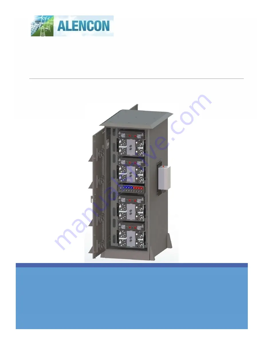
SPOT & BOSS BOX – V2: User Manual
Alencon Systems Integrated Form Factor for Paralleling Multiple SPOT or BOSS units in an Outdoor Rated Container.
Страница 1: ...Passionate About Power COPYRIGHT 2021 ALENCON LLC INC ALL RIGHTS RESERVED SPOT BOSS BOX V2 User Manual Alencon Systems Integrated Form Factor for Paralleling Multiple SPOT or BOSS units in an Outdoor...
Страница 2: ...pyright Information Any product names listed in this manual that are not registered trademarks of Alencon Systems LLC and or organization names mentioned may be trademarks and or registered trademarks...
Страница 3: ...not be liable for any incidental or consequential damages under any circumstances Specifications are subject to change without notice Every attempt has been made to make this document complete accura...
Страница 4: ...chanical Specifications 11 6 Installation 12 6 1 Installation Criteria 12 6 1 1 Required Tools List 12 6 1 2 Customer Supplied Hardware 12 6 2 Installation Procedure 13 6 2 1 Unpacking and Mounting BO...
Страница 5: ...CE 34 9 1 System Overview 34 Appendix A Safety Precautions 35 A 1 Degree of Danger Symbols 35 A 2 Electrical hazards 35 A 2 1 Electric shock from live voltage 35 A 2 2 Danger due to Battery Voltage 36...
Страница 6: ...FIGURE 12 SPOT BOSS WITH FEED AND MOUNTING BRACKETS 20 FIGURE 13 SPOT BOSS RACK MOUNTING BRACKETS 20 FIGURE 14 SPOT PLACEMENT MAP 21 FIGURE 15 JBOX LOCATION WITH MOUNTING HARDWARE 22 FIGURE 16 JBOX L...
Страница 7: ...zed by Alencon System or which have been subject to misuse abuse accident or improper installation This warranty does not cover the repair or replacement of any goods which fail as a result of damage...
Страница 8: ...iginal packaging material it was shipped in a fully completed Repair and Replacement Order Card and a photocopy proof of purchase date such as your sales receipt in a shippable container A product ret...
Страница 9: ...System Hardware 1 Rack Mounted JBOX Junction Box configured for customer application 1 4 SPOT BOSS units with FEED configured for customer application each unit numbered and marked on the box 4 4 SPOT...
Страница 10: ...70 and OSHA requirements 1 Before installing and using the BOX read all instructions presented in this manual and the cautionary markings shown on the enclosure 2 During operation hazardous voltages a...
Страница 11: ...econdary connection 4 2 JBOX Single Point of Input Output Alencon s JBOX junction box is a customizable combiner where electrical connections in and out of the BOX system land Speak to your Alencon re...
Страница 12: ...s FIGURE 2 BOX CABINET ENCLOSURE 45U 19 BOX Number of SPOT of BOSS Units Up to 4 Weight without SPOT or BOSS Units 250 KG Dimensions W x D x H 904 x 1210 x 2242 MM Electrical Specifications See indivi...
Страница 13: ...ation is required during the process please contact Alencon Systems LLC for assistance see Appendix C 6 1 1 Required Tools List Hammer Drill Masonry Drill Bit Appropriate size for customer supplied an...
Страница 14: ...X The BOX cabinet will arrive on a pallet Figure 3 3 Remove packaging and unbolt the enclosure from the pallet FIGURE 3 BOX CABINET ENCLOSURE MODEL 45U 19 Position cabinet on concrete pad Use 4 diamet...
Страница 15: ...ed boxes in Figure 5 and Figure 6 are available for cable ingress into the cabinet Visual Inspection of enclosure hardware clearance is mandatory to avoid interference along edges and corners of detai...
Страница 16: ...Alencon BOX V2 User Manual 15 P a g e FIGURE 6 CONDUIT ACCESS VIEW FROM BOTTOM OF CABINET...
Страница 17: ...late is designed to be mounted on standard 1 5 8 channel Unistrut Figure 8 FIGURE 7 PODD UNIT 3 VIEWS Customer supplied Unistrut must be mounted 20 apart on centerline Figure 88 Hang the PODD mounting...
Страница 18: ...provide access to the customer designated network SCADA system Installation will require routing a CAT cable from inside the BOX to the PODD Drill hole to be used for routing CAT cable from inside ca...
Страница 19: ...ied connection will provide access to the customer designated network SCADA system Typically this is routed through the conduit entry in a separate conduit from high voltage cables FIGURE 10 PODD MOUN...
Страница 20: ...2 4 Install Shelves into Enclosure The BOX enclosure is shipped with shelves already mounted on the interior 19 rack FIGURE 11 RACK SHELVES MOUNTED IN BOX CABINET The shelf orientations are different...
Страница 21: ...unpackaged and lifted onto a table or work bench to attach mounting brackets Figure 1313 Using 4 of the provided 20 x 3 4 Self Tapping Type F Bracket Mounting Screws securely attach the left and right...
Страница 22: ...hould be matched to the diagram in Figure 1414 Otherwise keep note of the installation order by SPOT BOSS serial number Leave the middle shelf of the rack unpopulated This will be used for the JBOX at...
Страница 23: ...OX LOCATION WITH MOUNTING HARDWARE 6 2 8 Connect Power Cables Within BOX Cabinet from JBOX Front to FEED Units Depending on the JBOX configuration wiring of the internal power cables may differ All ca...
Страница 24: ...terminals are designated by o Location 1 2 3 or 4 within the BOX see Figure 17 o Primary or Secondary connection o Positive or negative polarity Cable terminations will usually match the color of the...
Страница 25: ...onnection in this case Connect JBOX to Primary Input FEED o 4 5 foot power cables with SurLokconnectorsconnect SPOT BOSSunits 1 and 4 to the JBOX o 4 4 foot power cables with SurLok connectors connect...
Страница 26: ...nectors connect SPOT BOSS units 2 and 3 to the JBOX Route all cables along the right side stanchion as shown in Figure 19 Secure all cables appropriately after installation FIGURE 19 SURLOK CABLING RO...
Страница 27: ...o corresponding Amphenol connectors on the FEED units Up to 4 pairs per SPOT BOSS unit o For primary side connections route stringed cable pairs along the left side stanchion o For secondary side conn...
Страница 28: ...onnects to one of the black Rebling terminals on the bottom right of the JBOX Black line routed to the right Connect Secondary Output cables Figure 2121 o Secondary Output Positive lead connects to on...
Страница 29: ...ONS TO JBOX DO NOT zip tie cables too tightly or bend around sharp edges as it may cause breaks in the cable insulation which could lead to leakage currents arcing or ground faults Customer Connection...
Страница 30: ...the box using 3 2 foot CAT cables with RJ 45 STP connectors o These cables route internally within the cabinet One end of the SPOT unit daisy chain will be connected to the PODD with the 6 foot cable...
Страница 31: ...nally replace the cap and grommet tightening to reseal the port FIGURE 23 PODD WIRING Carefully reinstall the cap without damaging the plastic thread to retain the waterproof seal Connect communicatio...
Страница 32: ...de of the JBOX back see Section 6 2 9 FIGURE 25 JBOX GROUNDING TERMINAL 6 3 2 Cabinet and Rack Grounding A grounding terminal block is bonded to the BOX cabinet inside the front door on the cabinet fl...
Страница 33: ...round Not properly grounding the SPOT can be dangerous for BOX operators FIGURE 27 SPOT BOSS UNIT GROUNDING 6 3 4 PODD Grounding The external ground lug is found next to the three RJ 45 connectors on...
Страница 34: ...te as expected please contact Alencon Systems technical support for assistance with troubleshooting see Appendix C 8 2 Replacement of the Air Filters Air filters are located directly behind each hoode...
Страница 35: ...IoT hardware and software solution for controlling and monitoring your alternative energy assets utilizing Alencon s PODD device The PODD can be used with other Alencon products including the SPOT an...
Страница 36: ...ad to severe or lethal injuries due to electric shock To avoid electric shock from live voltage Wear class 2 personal protective equipment Always perform work in compliance with the regulations specif...
Страница 37: ...damaged equipment Operating damaged equipment can lead to hazardous situations that may result in serious or lethal injuries caused by electric shock To avoid electric shock from damaged equipment Onl...
Страница 38: ...tenance on the BOX only when the environment is dry and free of dust Always cover electrical bus channel prior activating the equipment A 3 3 Danger to life due to electric shock when the equipment is...
Страница 39: ...tion RTU Remote Terminal Unit Microprocessor controlled electronic protocol to exchange data with other devices SCADA Supervisory Control and Data Acquisition system Performed by transmitting telemetr...
Страница 40: ...ntact your distributor sales representative or Alencon Systems technical support if you need additional assistance Please have the following information ready before you call Product name serial numbe...