20
2480 Remote Intensifier Tooling Alcoa Fastening Systems
17
16
18
63
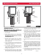
(2)
View is shown with
two
Reservoirs
(66)
in
place. When removed, Reservoirs are replaced by two Reservoir Plugs (75) as shown in figure
9a
(above).
5
6
12
19
4
1
2
3
8
9
10
11
73
72 71
75
(2)
VIEW
A
-A
45
(3)
44
43
42
46
47
48
49
41
51
50
40
39
83
37
(3)
80
36
76
55
78
22
74
68
20
64
63
To
Air
Trigger
69
(4)
66
(2)
67
65
52
90
31
71
(2)
21
70
(2)
53
54
See Det
ail
See Det
ail
See Det
ail
81
77
88
74
(2)
82
79
89
91
(2)
97
98
(2)
See Det
ail
A
A
68
Ref.
20
Ref.
72
Ref.
75
Ref.
Figure 9a
View of Intensifier top with T
op Guard in Place
96
(2)
95
70
Ref.
28
24
25
29
30
23
24
25
27
26
35
34
38
(2)
33
32
7
8
13
14
15
98
99
(4)
100
(4)
1
9
Figure 9a
59
60
61
62
58
57
56
55
54 - (Gland Assembly)
R
P
RETURN
PULL
90
- (Pull
G
land
Assembly)
PULL
RETURN
22 - (Return
Gland
Assembly)
31 - (Piston Assembly)
RETURN
PULL
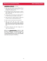
Figure 14

