15
2480 Remote Intensifier Tooling Alcoa Fastening Systems
ASSEMBLY OF BASE
(Figures 10 & 14)
NOTE: See F
ILL
AND
B
LEED
P
ROCEDURE
FOR
D
ISASSEMBLED
T
OOLS
before proceeding.
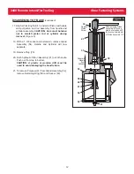
1. Insert Plug (78).
2. Holding handle inverted in a vice, Place Cylinder
(53) on Handle (21) with Dowel (79) and Plug (78)
with O-Rings (74) in place
positioned in matching
holes.
(Figure 10a)
3. Assemble Gland Assembly (54) with Vibratite
505125. Screw complete Gland Assembly into
Handle. Torque to 100-120 ft. lbs. using 1-3/8 socket
wrench.
(Figure 10b)
4. Push Air Piston/Rod assembly with Quad Ring (50)
in place into Air Cylinder (51) until it bottoms at top
of Cylinder (53).
(Figure 10b)
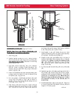
5. Turn tool upright. Install Hydraulic Piston (34)
(with
O-ring (33) and Back-up rings (38) in place)
in
handle. Press in from top of handle taking care not
to damage seals.
(Figure 14)
6. Push Screw (32) with O-ring (35) in place through
Hydraulic Piston (34) and screw into top of piston
rod. Hold Nut (41) with 9/16 socket and extension
and torque Screw (32) using 7/64 hex key to 55-60
in. lbs. Torque Nut (41) to 28-32 ft. lbs.
7. Hold handle in vise with bottom facing up. Push
Cylinder Head (49) with O-ring (48) in place squarely
into cylinder. Install Retaining Ring (47).
8. Position O-ring (44) and Muffler (43) on center of
Cylinder Head (49). Place Gasket (46) on Cylinder
Assembly (53).
NOTE: Lip must face Bottom Plate
(42).
Place Muffler End Cap (42) on top of Gasket
(46) and secure with 3 Button Head Screws (45)
using 1/8 hex key.
9. Turn tool upright. Install O-Ring (74) at top of Handle
(21).
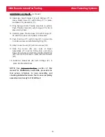
10. Install O-rings (24 & 30) & Back-up Rings (25 & 29) on
Pull Gland (28) Install O-rings (24 & 26) & Back-
upRings (25 & 27) on Return Gland (23). Push Gland
Assemblies into Manifold Block (68).
NOTE: Be sure
that all O-rings and Back-up Rings are in place
and oriented correctly on the Glands prior to
assembling.
11. Push Manifold Block down on Handle (21). Place tool
in a vise Head down and install 4 Screws (69) and
torque to 170 inch pounds.
continued
78
74
(2)
21
53
79
Press Handle (21) and Cylinder (53) together with Dowel (79) and Plug (78) in place.
Figure 10a
Figure 10b
41
51
50
52
53
54
Torque to
100-120 ft.lbs.
Figure 10


