14
2480 Remote Intensifier Tooling Alcoa Fastening Systems
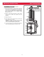
Left half of
Handle (19)
Right half of
Handle (19)
Locknut
(100)
Qty. 4
Hydraulic Hoses
(63)
Qty. 2
Air Trigger
and Hose
Assembly (1)
Socket Head
Cap Screw (99)
Qty. 4
Head
Assembly
Built-in
Strain
Relief
Figure 9
ASSEMBLY OF HEAD
(continued)
7. Assemble Hydraulic Hoses to Cylinder head
assembly. Use SLIC-TITE TEFLON thread
compound, or equivalent, on pipe threads.
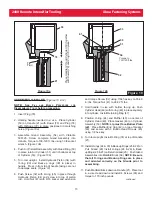
8. Assemble Air Trigger Assembly as follows
: (Figure 3)
NOTE: For ease of assembly, heat end of hose
before pushing onto fittings. When using a new
quick disconnect, remove and discard plastic
ferrule from nut before attaching air hose to
quick disconnect.
a.) Push O-Ring 500777 over threads of Trigger
Body.
b.) Push Trigger Stem through Trigger Body, then
Stretch O-Ring 500772 over Trigger Stem and
into first groove.
c.) Screw Trigger Body with Stem in place into
Trigger Housing.
d.) Screw Hose Fitting into Trigger Housing. Push Air
Hose onto Hose Fitting.
e.) Slide Quick Disconnect nut over Air Hose. Push
Hose onto Quick Disconnect and tighten nut.
9. Assemble Handle as follows
: (Figure 9)
a.)
Position Air Trigger Assembly into left handle half.
Press air hose into handles built-in strain relief.
b.) Position assembled Cylinder and hoses in left
handle half. Align right handle half with left
(locators help align halves).
c.) Insert Locknuts and Screws into Handle. Tighten
Screws.


