12
2480 Remote Intensifier Tooling Alcoa Fastening Systems
DISASSEMBLY OF BASE
(continued)
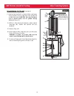
17. Grip Self-locking Nut (41) under Air Piston with pliers
and pull piston and rod assembly from handle and
cylinder assembly.
CAUTION: Care must be taken
not to scratch piston rod or cylinder during
removal. (Figure 6)
18. With a 1 3/8 socket and extension, remove Gland
Assembly (54). Handle and Cylinder will now
separate.
19. Remove Plug (78).
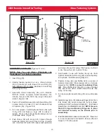
20. Push hydraulic Piston Assembly (31) out of handle.
Push out from top to bottom.
CAUTION: A plastic or wooden drift must be
used to avoid damaging the handle bore.
21. To remove Polyseal (61) from Gland Assembly (54),
remove Retaining Ring (59) and Spacer (60).
32
41
78
31
21
53
54
Remove
Piston
Screw
After removing Gland
Assembly (54), use a
plastic or wooden drift
to press out remainder
of Piston Assembly (31).
52
61
60
59
Separate
Handle
from
Cylinder
Figure 6


