


Albalá Ingenieros | Manual
FRS3004C02
mounting frame.
7 - Affix the main board to the mounting frame using the two screws included on the
front panel.
After these steps, the module is ready to be connected to other equipment.
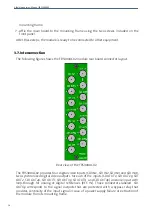
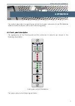
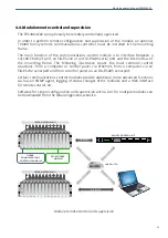
3.7. Interconnection
The following figure shows the FRS3004C02 module rear board connector layout.
Rear view of the FRS3004C02
The FRS3004C02 provides four digital video inputs (SDI IN1, SDI IN2, SDI IN3 and SDI IN4),
two synchronized digital video outputs for each of the inputs (SDI OUT1, SDI OUT1p, SDI
OUT2, SDI OUT2p, SDI OUT3, SDI OUT3p, SDI OUT4 and SDI OUT4p) and one input with
loop-through for analog or digital references (REF. IN). Those connectors labeled SDI
OUTXp correspond to the signal outputs that are protected with a bypass relay that
provides continuity of the input signal in case of a power supply failure or extraction of
the module from its mounting frame.
14
Содержание FRS3004C02
Страница 2: ...FRS3004C02 ...
Страница 4: ...FRS3004C02 ...
Страница 7: ...Albalá Ingenieros Manual FRS3004C02 1 3 Block diagram 7 ...
Страница 8: ...Albalá Ingenieros Manual FRS3004C02 FRS3004C02 8 ...
Страница 10: ...Albalá Ingenieros Manual FRS3004C02 Approximate weight 350 g 10 ...
Страница 16: ...Albalá Ingenieros Manual FRS3004C02 FRS3004C02 16 ...
Страница 26: ...Albalá Ingenieros Manual FRS3004C02 FRS3004C02 26 ...
Страница 28: ...Albalá Ingenieros Manual FRS3004C02 FRS3004C02 28 ...
Страница 30: ...Albalá Ingenieros Manual FRS3004C02 FRS3004C02 30 ...
Страница 32: ...Albalá Ingenieros S A Medea 4 28037 Madrid Spain 34 913274453 www albalaing com info albalaing com ...


