background image


Technical Reference Manual for 

OMNI-A0092


Author  

C. Vale 

Creation Date 

2010-04-29 

Product 

OMNI-A0092 

Revision Date 


Name:OMNI-A0092_TRM.doc 

Company Confidential 

Version 1.0 

Page 15 of 55 


2.2.1.1


Installation of pressure hose 

The pressure hose used to actuate the mast is pre-installed on the main antenna assembly. The 
hose should be routed through the hole in  the base plate provided near the AMU and to  the 
compressor,  where  it  should  be  attached  to  the  air  pressure  nozzle.  Care  should  be  taken  to 
ensure that the hose is not pinched. 

2.2.1.2


Installation of power to compressor 

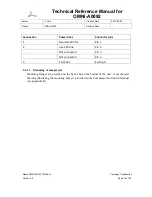
Power is provided to the compressor unit via the power connector provided. The table below 
provides the required wiring of the power cable (not provided) to the connector. 

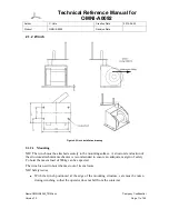
Figure 10: Power connector with cable attached (not provided)


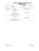
Figure 11: Remote control with cable 


Содержание OMNI-A0092

Страница 1: ...e Creation Date 2010 04 29 Product OMNI A0092 Revision Date Name OMNI A0092_TRM doc Company Confidential Version 1 0 Page 1 of 55 Product code OMNI A0092 File name OMNI A0092_TRM doc Version 1 0 PREPARED BY C Vale TECHNICAL REFERENCE MANUAL FOR OMNI A0092 ...

Страница 2: ...agram 5 Figure 3 Items to be bolted to mounting surface e g container 6 Figure 4 Detail of mechanical interface for bolting down the main antenna assembly 7 Figure 5 Top view of main antenna assembly 9 Figure 6 Winch installation drawing 11 Figure 7 Anchor fitting 13 Figure 8 Compressor 14 Figure 9 Power connector 14 Figure 10 Power connector with cable attached not provided 15 Figure 11 Remote co...
Страница 3: ... 0 Page 2 of 55 Responsible Persons Name Designation Contact Signature Chris Vale Electronic Engineer Rudolf van Rooyen Mechanical Engineer Approval Sheet Name Designation Date Signature Chris Vale Business Unit Manager Francois Havenga Configuration Controller Francois Havenga QA Manager Document history Section Pages Date Version Author All All 2010 04 29 1 0 C Vale ...

Страница 4: ... MHz frequency range The antenna is equipped with an efficient matching unit which provides excellent VSWR characteristics across the band with maximal efficiency The antenna is designed to be mounted on the roof of a vehicle or shelter and deploys pneumatically in a fully automatic fashion in a very short period of time requiring only two people to deploy When stowed the low profile of the antenn...

Страница 5: ... to deploy and retract the antenna The items must be mounted securely and positioned judicially to ensure the safest possible configuration Incorrect or inadequate installation could result in damage to the antenna and injury or death to the personnel operating the antenna The following items can be placed at the discretion of the installer or operator but should be located in a cool well ventilat...

Страница 6: ...ence Manual for OMNI A0092 Author C Vale Creation Date 2010 04 29 Product OMNI A0092 Revision Date Name OMNI A0092_TRM doc Company Confidential Version 1 0 Page 5 of 55 Figure 2 OMNI A0092 Antenna system block diagram ...

Страница 7: ... firmly to the roof of the container The main antenna assembly must be bolted to the roof of the container in 40 places The winch is used to raise the antenna mast to the vertical position and is a heavily loaded item up to 500kg of pulling load can be expected The high pulling load on the winch must be catered for in the design of the attachment of the winch to the roof of the container Anchors f...

Страница 8: ...nterface for bolting down the main antenna assembly 2 1 1 1 Mounting The main antenna assembly must be bolted down by its base plate This is a 8mm thick plate that flanges out at the base of the enclosure 40 bolt holes of 8 5mm diameter are provided around the perimeter of the enclosure The bolt holes are all equi spaced 250mm apart with the corner holes spaced 45mm apart in the x and y direction ...

Страница 9: ...mbly can be mounted flush with the back of the mounting platform Also take note that space no less than 0 5m is recommended to the sides of the main antenna assembly is necessary to provide a location for the guy rope anchoring brackets 2 1 1 4 Lifting of the main antenna assembly The main antenna assembly is a large and heavy unit that needs special care when being handled The unit is 4114mm long...

Страница 10: ...it on top of the steel bracket securing the sprung rollers The second pair is located inside the enclosure mounted directly to the base plate on either side of the securing clamp Figure 5 Top view of main antenna assembly It is recommended that a sling be used for lifting The recommended slinging angle is 45 Special care should be taken using the sling with the eye bolts at the rear hard points to...

Страница 11: ... the auxiliary antenna from the provided port on the top lid of the AMU is not provided Should the provided RF cable not be of sufficient length or become damaged they can be replaced with new or longer cable of similar power handling capacity close to at least 1 5kW up to 30MHz for the cable used to power up the OMNI A0092 antenna and an adequate power handling to manage the power to be transmitt...

Страница 12: ... The winch must be attached securely to the mounting surface A structural evaluation of the structure attachment mechanics is recommended to ensure an adequate margin of safety To hoist the mast a load of 500kg can be expected The winch is used to hoist the mast out of its enclosure NB Safety issues With the winch positioned at the edge of the mounting structure care must be taken during winching ...

Страница 13: ...ole of the main antenna assembly The gin pole is secured via a hinged joint to the hinge plate of the antenna assembly and via a permanently installed length of rope running from the top hole of the gin pole to a collar at the top of the bottom mast section The antenna has been designed to allow the rope connection from the winch to the antenna to be permanent so the main antenna assembly enclosur...

Страница 14: ...the anchor points The anchors must therefore be securely attached to the mounting structure A structural evaluation of the roof structure attachment mechanics is recommended Figure 7 Anchor fitting 2 1 3 1 Location The two laterally positioned fittings one on each side of the mast must be mounted in line with the mast when it is in the upright position The fittings must be positioned as close as i...

Страница 15: ...dix B Compressor Instruction Manual Compressed air is required to extend the mast A dedicated compressor is supplied as part of the OMNI A0092 system The compressor is driven by 220V 50Hz AC power The compressor is controlled via a small remote control box The remote control box is connected to the compressor by means of a 5 meter cable Figure 8 Compressor REMOTE CONTROL CONNECTION POWER CONNECTOR...

Страница 16: ...se should be routed through the hole in the base plate provided near the AMU and to the compressor where it should be attached to the air pressure nozzle Care should be taken to ensure that the hose is not pinched 2 2 1 2 Installation of power to compressor Power is provided to the compressor unit via the power connector provided The table below provides the required wiring of the power cable not ...

Страница 17: ...e 16 of 55 Connection Power lines Connector pins 1 Neutral 220V AC Pin 1 2 Live 220V AC Pin 2 Not connected Pin 3 Not connected Pin 4 3 Earth line Earth pin 2 2 1 3 Mounting of compressor Mounting flanges are provided on the back and on the bottom of the unit A mechanical drawing illustrating the mounting holes is provided in the Compressor Instruction Manual see appendix B ...

Страница 18: ...environment Also refer to the documentation accompanying the load for more detailed installation instructions Figure 12 Schematic of the RF load unit 2 2 2 1 Mounting 2 2 2 1 1 Free standing The unit can be used as a free standing unit In this configuration it stands on its lower feet The feet provided on the back are intended for handling and cannot be used during operation as the space would be ...

Страница 19: ...F cable runs from the port on the AMU labelled TO MATCHING LOAD to the N connector on the back of the RF load The cable must be routed through the hole on the base plate of the main antenna assembly and should not be subjected to over bending and pinching during installation The antenna should never be used at frequencies below 7 MHz if the load is not attached The load is necessary to provide ade...

Страница 20: ...pany Confidential Version 1 0 Page 19 of 55 Alarm state Description Alarm signal pin states Off Power supply to the load is operational AND Temperature is within normal operating parameters A B open B C closed shorted On Power supply to the load has failed OR The load temperature has exceeded acceptable parameters A B closed shorted B C open ...

Страница 21: ...l times by the operator s and gloves must be worn to protect hands 3 1 1 Site selection 1 Select a site for deployment which is as flat as possible with minimal obstructions The slope of the ground should be no more than 10 2 The antenna is designed to be deployed in a tactical fashion even from the roof of a vehicle without any support guy ropes required other than the ones connected directly to ...

Страница 22: ...ving the antenna deployed in a lightning storm Due to the antenna s height there is a very high likely hood of it attracting a direct strike which could cause damage to equipment and injury or death to nearby personnel 3 1 3 Prepare for secondary guy ropes optional 1 If it is desired to make use of the longer secondary guy ropes for operation in high winds then the field should be spiked with the ...

Страница 23: ...k the mast by loosen the knob that secures the mast to the base plate The securing clamp is located at the back of the enclosure 2 Turn the knob anti clockwise to loosen and allow it to swing back to the position shown the picture below Figure 13 Loosening the mast securing clamp Failure to loosen the securing clamp will result in fatal damage to the antenna when deployment is attempted and probab...

Страница 24: ...or is off 2 The mast can be hoisted up by turning the winch handle in a clockwise direction Figure 14 The antenna just before hoisting out of the enclosure 3 If the winch operator is having difficulty operating the winch it may need to be greased See the maintenance section below 4 The first stop position is when the mast has been raised by about 30 degrees from the horizontal by means of the winc...

Страница 25: ...bottom mast section Note that typically these guy ropes can be left secured to the mast in this fashion even when the mast is stowed in the enclosure for ease of access and to speed up deployment 3 1 8 Attach auxiliary equipment optional 1 An optional clip on bracket may have been supplied that is attached to the top of the mast 2 The clip on bracket is secured to the top of the mast using the spr...

Страница 26: ...hen this point comes 3 NB It is the purpose of the winch only to hoist the antenna to the vertical position not to tension the guy rope system Over tightening the winch can damage the antenna The winch provided is extremely geared and it is easily capable of destroying the antenna assembly if it is over tightened at this stage Continued tightening of the winch will eventually lead to failure of th...

Страница 27: ... 13 Extend the mast 1 The mast can now be extended by using the remote control of the compressor 2 Push the button to the up position When the mast is being erected the air supply must be manned at all times 3 While the mast is been erected make sure all cables are free and not tangled Stop immediately in case a cable gets stuck or tangled by setting the remote control button to the middle positio...

Страница 28: ...nnel can guide the secondary guy ropes and auxiliary antenna cables if necessary 7 The compressor will automatically stop when the pre set pressure is reached 8 Leave the remote control stick in the up direction whilst the antenna is deployed and operated as this will allow to compressor to periodically re pressurise the mast on continuous bases as it loses pressure over time 3 1 14 Secure the sec...

Страница 29: ...e radiator is the part of the antenna constituting the following mast steel wires gin pole and hinge The ground constitutes objects such as the base plate and mounting structure the sprung rollers the winch and securing clamp at the back of the enclosure b The mechanism has properly and fully deployed c The guy ropes are secure and there is no chance of the antenna collapsing d The antenna is not ...

Страница 30: ...ditions at low frequencies from 1MHz to 6MHz most of the energy delivered to the antenna is dumped to the load Above 6MHz the situation is reversed and only about 10 20 of the power delivered to the antenna is dumped to the load Nevertheless the sense port can provide an indication of the operation of the device is so needed 3 2 2 1 Protection measures The antenna is equipped with protection measu...

Страница 31: ...st stand clear of the mast as it retracts as the radial arms can cause serious injury as they fold and stow near the end of the process All personnel should stand a safe distance from the mast to ensure they are not injured by the moving parts as the antenna retracts 6 It is normal for the radial arms to make a loud impact noise against the mast as they stow against the mast 7 After the mast is fu...

Страница 32: ...damaged during transportation over rough roads 14 Stow the loose primary guy ropes in the enclosure alongside the mast 15 Allow the winch to be further loosened to allow the gin pole to fully fold down against the mast 16 Ensure that the winch rope is lying in the notch provided at the front of the enclosure 17 Close the lids of the box and secure the latches on either end of the box 18 Dismantle ...

Страница 33: ... Date 2010 04 29 Product OMNI A0092 Revision Date Name OMNI A0092_TRM doc Company Confidential Version 1 0 Page 32 of 55 4 Suggested storage and handling If the antenna is not used it should be stored in the packaging box that it was provided in in a cool dry place ...

Страница 34: ...bly can be completely removed whilst the antenna remains installed To do this remove the nyloc nuts holding the enclosure down and lift the enclosure off the antenna Once cleaning is complete the enclosure can be replaced Note that the enclosure is not supposed to accomplish a watertight seal between it and the base plate Water is supposed to drain out of the enclosure in the gap between the base ...

Страница 35: ...a Clark Mast The service manual for the mast is included in section 7 Appendix A 5 4 Fuse replacement The AMU is equipped with a number of protection measures to ensure the antenna can survive surges over current and over voltage The over current protection is accomplished via fuse A spare 16A fuse has been included with the antenna accessories In the event that the fuse needs to be replaced caref...

Страница 36: ...idential Version 1 0 Page 35 of 55 6 Specifications 6 1 Electrical specifications Property Value Efficiency See Figure 18 Frequency 1 30 MHz VSWR 2 5 1 See Figure 17 Feed power handling Watts 1000 W Nominal input impedance Ohms 50 Ω Connector N type female Polarisation Vertical 6 2 Plots illustrating the electrical performance Figure 17 Measured VSWR ...

Страница 37: ...cal Reference Manual for OMNI A0092 Author C Vale Creation Date 2010 04 29 Product OMNI A0092 Revision Date Name OMNI A0092_TRM doc Company Confidential Version 1 0 Page 36 of 55 Figure 18 Antenna efficiency ...

Страница 38: ...rsion 1 0 Page 37 of 55 6 3 Mechanical specifications Property Value Weight kg 330 kg antenna 60 kg accessories Total including packaging 550Kg Dimensions when deployed Max diameter 5m 0 5m Height 8 0m 0 5m Dimensions when stowed excl winch Length 4 1m Width 0 62m Height 0 5m Passivation Alodined then paint Anodised Sand blasted stainless steel Painted E glass ...

Страница 39: ... Version 1 0 Page 38 of 55 Environmental specifications Property Value Wind survival 120 km h With all guys supports Temperature operational 30º C to 51º C Temperature storage 30º C to 71º C Vibration ground transportation MIL STD 810E Method 514 5 Cat 1 Vibration operational MIL STD 617 1 Type 1 Water ingress rating MIL STD 820F 506 4 IP65 except enclosure ...

Страница 40: ...M doc Company Confidential Version 1 0 Page 39 of 55 Material specifications Component Material Mast Aluminium passivated Radiating elements Stainless steel braided wire Mounting brackets Stainless steel Support braces clamps and hinge mechanism Stainless steel plate Ground plane Aluminium plate passivated Enclosure Painted E Glass ...

Страница 41: ...erence Manual for OMNI A0092 Author C Vale Creation Date 2010 04 29 Product OMNI A0092 Revision Date Name OMNI A0092_TRM doc Company Confidential Version 1 0 Page 40 of 55 7 Appendix A Clark Mast Maintenance Manual ...

Страница 42: ...Technical Reference Manual for OMNI A0092 Author C Vale Creation Date 2010 04 29 Product OMNI A0092 Revision Date Name OMNI A0092_TRM doc Company Confidential Version 1 0 Page 41 of 55 ...

Страница 43: ...Technical Reference Manual for OMNI A0092 Author C Vale Creation Date 2010 04 29 Product OMNI A0092 Revision Date Name OMNI A0092_TRM doc Company Confidential Version 1 0 Page 42 of 55 ...

Страница 44: ...Technical Reference Manual for OMNI A0092 Author C Vale Creation Date 2010 04 29 Product OMNI A0092 Revision Date Name OMNI A0092_TRM doc Company Confidential Version 1 0 Page 43 of 55 ...

Страница 45: ...Technical Reference Manual for OMNI A0092 Author C Vale Creation Date 2010 04 29 Product OMNI A0092 Revision Date Name OMNI A0092_TRM doc Company Confidential Version 1 0 Page 44 of 55 ...

Страница 46: ...Technical Reference Manual for OMNI A0092 Author C Vale Creation Date 2010 04 29 Product OMNI A0092 Revision Date Name OMNI A0092_TRM doc Company Confidential Version 1 0 Page 45 of 55 ...

Страница 47: ...Technical Reference Manual for OMNI A0092 Author C Vale Creation Date 2010 04 29 Product OMNI A0092 Revision Date Name OMNI A0092_TRM doc Company Confidential Version 1 0 Page 46 of 55 ...

Страница 48: ...Technical Reference Manual for OMNI A0092 Author C Vale Creation Date 2010 04 29 Product OMNI A0092 Revision Date Name OMNI A0092_TRM doc Company Confidential Version 1 0 Page 47 of 55 ...

Страница 49: ...Technical Reference Manual for OMNI A0092 Author C Vale Creation Date 2010 04 29 Product OMNI A0092 Revision Date Name OMNI A0092_TRM doc Company Confidential Version 1 0 Page 48 of 55 ...

Страница 50: ...Technical Reference Manual for OMNI A0092 Author C Vale Creation Date 2010 04 29 Product OMNI A0092 Revision Date Name OMNI A0092_TRM doc Company Confidential Version 1 0 Page 49 of 55 ...

Страница 51: ...erence Manual for OMNI A0092 Author C Vale Creation Date 2010 04 29 Product OMNI A0092 Revision Date Name OMNI A0092_TRM doc Company Confidential Version 1 0 Page 50 of 55 8 Appendix B Compressor Instruction Manual ...

Страница 52: ...Technical Reference Manual for OMNI A0092 Author C Vale Creation Date 2010 04 29 Product OMNI A0092 Revision Date Name OMNI A0092_TRM doc Company Confidential Version 1 0 Page 51 of 55 ...

Страница 53: ...Technical Reference Manual for OMNI A0092 Author C Vale Creation Date 2010 04 29 Product OMNI A0092 Revision Date Name OMNI A0092_TRM doc Company Confidential Version 1 0 Page 52 of 55 ...

Страница 54: ...Technical Reference Manual for OMNI A0092 Author C Vale Creation Date 2010 04 29 Product OMNI A0092 Revision Date Name OMNI A0092_TRM doc Company Confidential Version 1 0 Page 53 of 55 ...

Страница 55: ...Technical Reference Manual for OMNI A0092 Author C Vale Creation Date 2010 04 29 Product OMNI A0092 Revision Date Name OMNI A0092_TRM doc Company Confidential Version 1 0 Page 54 of 55 ...

Страница 56: ...Technical Reference Manual for OMNI A0092 Author C Vale Creation Date 2010 04 29 Product OMNI A0092 Revision Date Name OMNI A0092_TRM doc Company Confidential Version 1 0 Page 55 of 55 ...

Отзывы: