Control
akYtec GmbH · Vahrenwalder Str. 269 A · 30179 Hannover · Germany Tel.: +49 (0) 511 16 59 672-0 · www.akytec.de
26
When the Autotuning is over, the
АT
indicator turns off and the Control mode is started. If
an error occurs during the Autotuning, the Control mode will be stopped and the indicator
А
T
starts to blink.
Note
:
–
Use the Autotuning only when the controlled system allows noticeable fluctuations of
the process value relative to the setpoint. Otherwise, the PID parameters should be
set manually (see 7.4) on the basis of existing information on the process inertia.
–
It is not recommended to modify the parameters during the Autotuning.
–
If Autotuning fails, stop control, restart the device and start the Autotuning again.
7.4
Manual Tuning
If the characteristics of the process are known, PID factors can be set manually.
The parameter
P
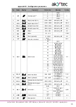
can be set in measuring units within the range 0.1…999.9 for tempera-
ture sensors (RTD and TC) and within the range 0.001…9999 for linear signals.
The parameter
i
can be set in seconds within the range 0…3999. If
i
= 0, the component I
is not included in the control algorithm.
The parameter
d
can be set in seconds within the range 0…3999. If
d
= 0, the component
D is not included in the control algorithm.
7.5
Manual Control
If Manual control is activated, the outputs of the controller are only controlled by the oper-
ator using the functional keys; also Remote start/stop is not available.
To use the Manual Control go to the
LmAn
menu group. To display the group in the
menu make sure that:
–
CntL =
Pid
–
Stand-alone control is activated (see 7.2)
–
At
= StoP
Otherwise the group
LmAn
doesn’t appear in the menu.
Press the key
to enter the group. Once the first parameter
o-Ed
(Manual output
signal) has been selected, the control will be stopped, the process value
Pv
displayed on
the upper display, the
o-Ed
on the lower display and the
MAN
indicator will flash on.
The output signal
o-Ed
can be modified within the range from
oL-L
to
oL-H
by using the
keys
and
.
The limitation by the Output signal ramp
orL
(see 6.9) can cause the deviation of the
Manual control (
o.
) from the Manual output signal (
o-Ed
). After the parameter
o-Ed
has
been set check if the Current output signal has reached the set value.
To switch between the parameters within the group press the key
.
To exit the Manual control mode press and hold down the key
> 3 sec. The device
will run the control mode specified in the parameter
r-L
(see 7.6).
7.6
Control over Network
If Network control is activated, the outputs are only controlled by the Master device. The
controller operates only as a Slave.
The device supports control via Modbus over RS485 interface with the protocols Modbus
RTU / Modbus ASCII.
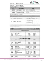
The supported Modbus functions are shown in the Table C.1.
The implemented Modbus Exception Codes are shown in the Table C.2.


