34
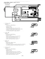
<MW/LW Adjustment>
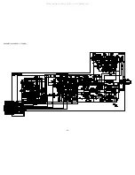
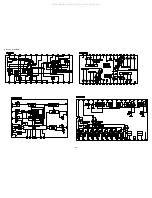
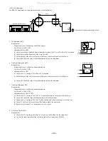
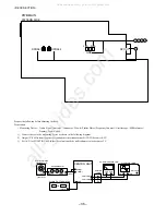
For MW/LW adjustment, do wiring and connection as in the following.
Rch
Lch
60cm
Standard Signal Generator
SET
TP
GND
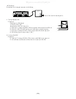
Connect to the respective measuring device
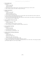
5. IF adjustment (MW)
Requirement
Measuring Device: Oscilloscope and Millivoltmeter
Test Point: Lch, Rch, GND
Adjustment Point: L802
(1) Adjust the setting of Standard Signal Generator (hereinafter S.S.G) to 450 kHz of 30 % variation.
(2) Adjust the reception frequency of the set to 999 kHz.
(3) While looking at the waveform on the oscilloscope, reduce the output level all the way.
(4) Adjust L802 until the value of the millivoltmeter reaches the maximum.
6. Tracking Adjustment (MW)
Requirement
Measuring Device: Oscilloscope and millivoltmeter
Test Point: Lch, Rch, GND
Adjustment Point: L951
(1) Adjust the S.S.G setting to 999 kHz of 30 % variation.
(2) While looking at the waveform on the oscilloscope, reduce the output level all the way.
(3) Adjust L951 until the value of the millivoltmeter reaches the maximum.
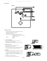
7. Tracking Adjustment (LW)
Requirement
Measuring Device: Oscilloscope and millivoltmeter
Test Point: Lch, Rch, GND
Adjustment Point: L941, TC942
(1) Adjust the S.S.G setting to 144 kHz, 30 % variation and reduce the output level all the way.
(2) Adjust L941 until the value of millivoltmeter reaches the maximum.
(3) Adjust the S.S.G setting to 290 kHz, 75 kHz variation, and reduce the output level all the way.
(4) Adjust TC942 until the value of the millivoltmeter reaches the maximum.
(5) Repeat the adjustment 2 or 3 times from step 1 to 4 above.
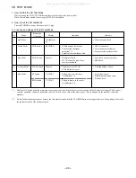
8. Auto Stop Check (MW)
Requirement
(1) Adjust the S.S.G setting to 999 kHz, 30 % variation, and 78 dBuV for the output level.
(2) Activate the tuner search function, and check that there is reception of 999 kHz.
OSCILLOSCOPE
Lch
Rch
GND
GND
CH2
CH1
CH2
CH1
GND
Lch
Rch
GND
AC MILLIVOLTMETER
All manuals and user guides at all-guides.com
Содержание XR-EM70
Страница 12: ...12 SCHEMATIC DIAGRAM 1 MAIN 1 2 PHONE OPTICAL HEAD All manuals and user guides at all guides com...
Страница 13: ...13 SCHEMATIC DIAGRAM 2 MAIN 2 2 AMP SECTION All manuals and user guides at all guides com...
Страница 18: ...18 SCHEMATIC DIAGRAM 4 CD CD DRIVE CD LOAD All manuals and user guides at all guides com...
Страница 20: ...20 SCHEMATIC DIAGRAM 5 TUNER All manuals and user guides at all guides com...
Страница 22: ...22 SCHEMATIC DIAGRAM 6 PT All manuals and user guides at all guides com...
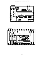
Страница 24: ...24 IC BLOCK DIAGRAM All manuals and user guides at all guides com...
Страница 25: ...25 All manuals and user guides at all guides com...

