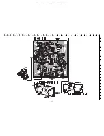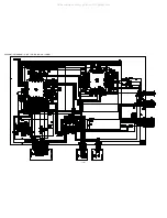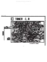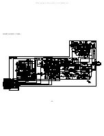
31
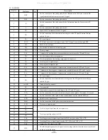
1
O-COIN
O
CD IC control data output.
2
O-CDCONT
O
CD block power ON / OFF control output.
3
O-OPEN (CD)
O
CD tray open data output.
4
O-CLOSE (CD)
O
CD tray close data output.
5
O-OPEN (CT)
O
Deck open / close output.
6
O-PL
O
Deck solenoid output.
7
I-AS
I
Deck auto stop signal input.
8
O-MOTOR
O
Deck motor ON / OFF output.
9
O-CLOSE (CT)
O
Deck open / close output.
10
O-CLKSFT
O
MICON clock shift control.
11
I-RESET
I
Reset input.
12
I-TU SIG
I
Tuner SD detect input.
13
I-CDSW (DOOR)
I
CD mecha switch A/D converter input.
14
VSS1
GND.
15
CF1
Connection of 9.43MHz oscillator.
16
CF2
Connection of 9.43MHz oscillator.
17
VDD1
Power supply input.
18
I-HOLD
I
Power failure detection input.
19
I-LEVEL
I
Signal level input.
20
I-STOP (HEAD)
I
Deck cam switch input and tape tray condition detect input.
21
I-CSTSW
I
Cassette tape and side A, B tab of cassette detect input.
22
I-ENC3 (VOL)
I
Volume rotary encoder A/D input.
23
I-ENC2 (TREBLE)
I
Treble rotary encoder A/D input.
24
I-ENC1 (BASS)
I
Bass rotary encoder A/D input.
25
I-KEY2
I
Key input. (A/D)
26
I-KEY1
I
Key input. (A/D)
27
I-TM BASE
I
Reference clock input for watch.
28
I-RDCL
I
RDS clock input. (EZ only)
29
I-RMC
I
System remote control signal input.
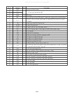
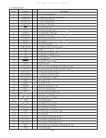
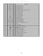
30 ~ 40
G11 ~ G1
O
FL grid G11 ~ G1 output.
41 ~ 45
P21 ~ P17
O
FL segment P21 ~ P17 output.
46
VDD3
Power supply input.
47 ~ 50
P16 ~ P13
O
FL segment P16 ~ P13 output.
51
VP
P
ower supply for FL display.
52 ~ 62
P12 ~ P2
O
FL segment P12 ~ P2 output.
63
LW/P1
I/O
LW diode input / FL segment P1 output.
64 ~ 67
NC
Not connected.
68
SI (ECHO)
Connected to GND through a resistor.
69
SLT (ECHO)
Connected to GND through a resistor.
70
SCK (ECHO)
Connected to GND through a resistor.
71
I-MIC
I
Microphone input. (Connected to GND through a resistor)
72
VDD4
Power supply input.
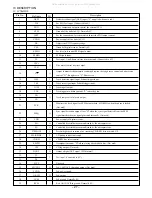
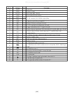
Pin No.
Pin Name
I/O
Description
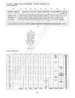
IC, LC876564V-5Y22
All manuals and user guides at all-guides.com
all-guides.com
Содержание XR-EM70
Страница 12: ...12 SCHEMATIC DIAGRAM 1 MAIN 1 2 PHONE OPTICAL HEAD All manuals and user guides at all guides com...
Страница 13: ...13 SCHEMATIC DIAGRAM 2 MAIN 2 2 AMP SECTION All manuals and user guides at all guides com...
Страница 18: ...18 SCHEMATIC DIAGRAM 4 CD CD DRIVE CD LOAD All manuals and user guides at all guides com...
Страница 20: ...20 SCHEMATIC DIAGRAM 5 TUNER All manuals and user guides at all guides com...
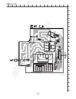
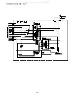
Страница 22: ...22 SCHEMATIC DIAGRAM 6 PT All manuals and user guides at all guides com...
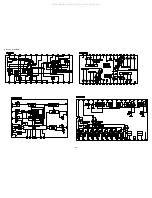
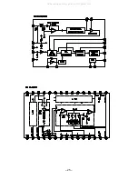
Страница 24: ...24 IC BLOCK DIAGRAM All manuals and user guides at all guides com...
Страница 25: ...25 All manuals and user guides at all guides com...

